

Page 1
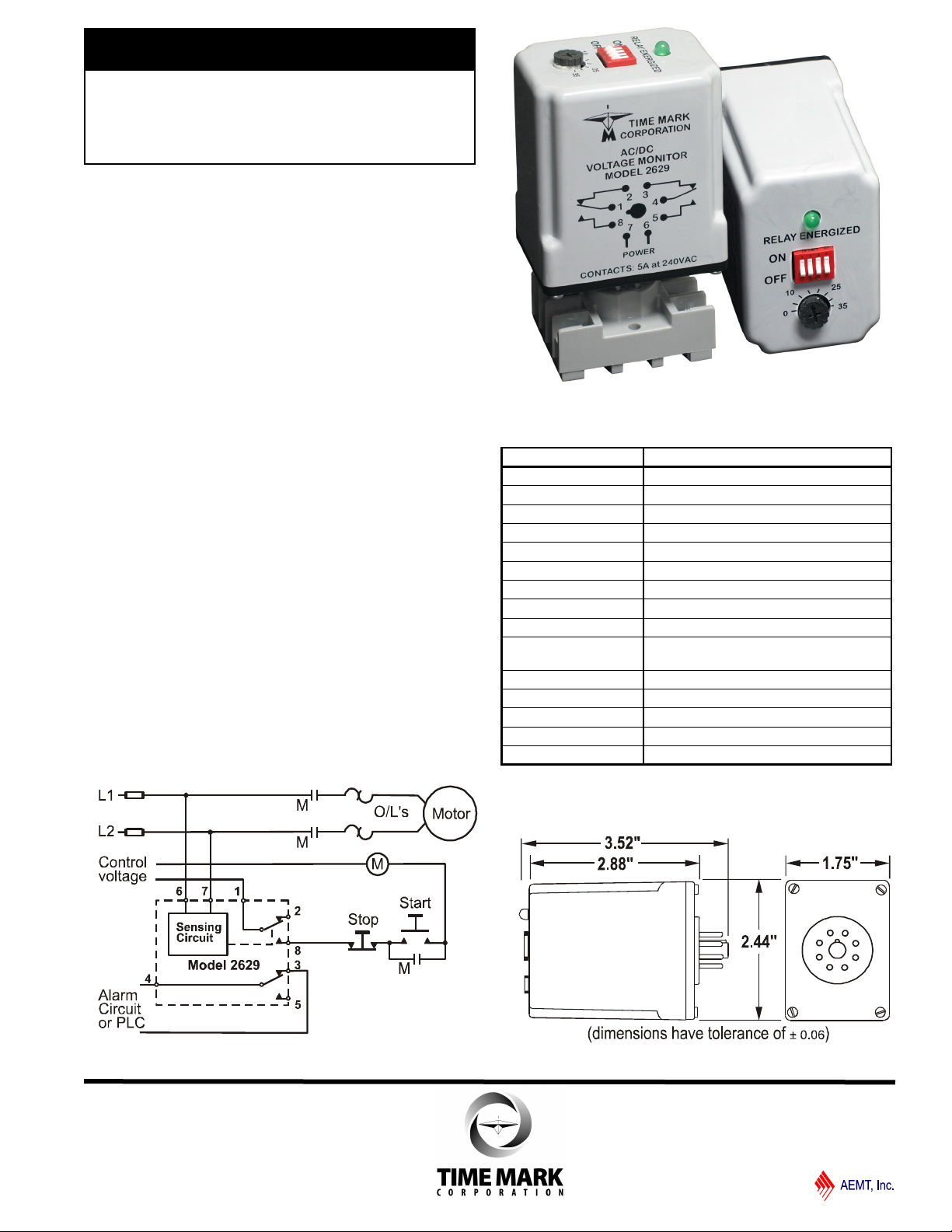
MODEL 2629
TIME MARK is a division of
AC/DC
Voltage Monitor
Monitors Over or Under Voltage
AC or DC from 15 to 260 Volts
Adjustable Trip Points
Automatic Reset
DPDT Relay
DESCRIPTION
The Model 2629 AC/DC Voltage Monitor is designed
to continuously monitor any AC or DC voltage from 15
to 260 volts.
Input voltages above the setpoint cause the output
contacts to energize. Input voltages below the setpoint
cause the output contacts to de-energize. The dead
band between pull-in and drop-out is less than 5%.
Dip switches are used on the Model 2629 to choose
between AC and DC voltage monitoring, and to select
one of the eight trip level ranges. Each trip level has a
user adjustable 35 volt range, with a 5 volt overlap
between the ranges. The unit has a screwdriver
adjustment to set the trip point within that 35 volt range.
TYPICAL APPLICATION
SPECIFICATIONS
Model 2629
Supply Voltage 15 to 260 VAC or VDC
Max Supply Voltage 280VAC or 300VDC
Power Consumption
Transient Protection 2500V for 10ms
Setpoint Stability ± 1%
Response Time 1 sec ON / 100ms OFF
Reset Type Automatic
Dead Band less than 5% all ranges
Contact Rating DPDT 5A at 240VAC resistive
Expected Relay Life Mech: 5 million operations
Elec: 100,000 at rated load
Operating Temperature -13º to +122º F
Humidity Tolerance 0-97% without condensation
Enclosure Material ABS plastic
Weight 5 oz.
Mounting 8-pin socket (*order separately)
1.5 watts max.
* Order 8-pin socket number 51X120
Sales (800) 862-2875
Main (918) 438-1220
DIMENSIONS
11/2011
© 2011 TIME MARK CORPORATION
Page 2
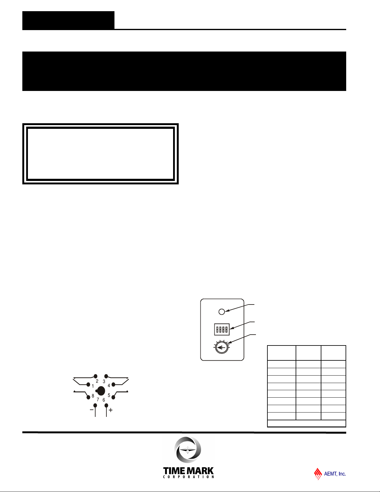
POWER
0
5
10
15
20
25
30
35
RELAY ENER GIZED
ON
OFF
—OPEN—
1 2 3 4
LED Indicator
Dip Switch
Dial adjustment
MODEL 2629
TIME MARK is a division of
AC/DC Voltage Monitor
READ ALL INSTRUCTIONS BEFORE INSTALLING, OPERATING OR SERVICING THIS DEVICE.
KEEP THIS DATA SHEET FOR FUTURE REFERENCE.
POTENTIALLY HAZARDOUS VOLTAGES ARE PRESENT AT THE TERMINALS OF THE MODEL 2629.
ALL ELECTRICAL POWER SHOULD BE REMOVED WHEN CONNECTING OR DISCONNECTING WIRING.
INSTALLATION
Connect the voltage to be monitored to the socket using
the Pin Diagram pictured on this data sheet and on the
unit as a reference (contacts are shown in the
de-energized condition).
The output contacts used will depend on whether the
Model 2629 is used to detect over-voltage or undervoltage, and whether the unit will shut off a load, or trip
an alarm.
The monitor’s internal relay will energize when the input
voltage is above the trip level setting. This allows the
unit to be set to detect over-voltage (relay will energize
on fault). The LED indicator will illuminate whenever
the relay is energized.
NOTE: When installing the Model 2629 Voltage Monitor in
areas of high humidity or contamination, it is recommended that
the base area and all exposed metal parts of the socket be coated
liberally with a good quality silicone grease, such as Dow Corning
DC-4 or DC-4X. Insert the unit into the socket and wipe off
excess grease around the base. This will prevent the entrance of
moisture and other contaminates into the base and socket areas.
PIN DIAGRAM
Sales (800) 862-2875
GENERAL SAFETY
THIS DEVICE SHOULD BE INSTALLED AND SERVICED BY QUALIFIED PERSONNEL.
Installation Instructions
WARNING
THE MODEL 2629 IS NOT TO BE USED IN
APPLICATIONS WHERE VOLTAGES
IN EXCESS OF 300VAC
ARE TO BE MONITORED OR SWITCHED.
Main (918) 438-1220
ADJUSTMENT PROCEDURE
Select the range where the desired trip voltage falls in
between the choices shown on the chart shown below. The
same Range Chart is also screened on the unit.
Set the dial to the difference between the desired voltage and
the low number selected.
TROUBLESHOOTING
Should the Model 2629 AC/DC Voltage Monitor fail to operate,
check all connections. Verify that the proper voltage is
present, and check all fuses. Should problems persist,
contact the factory at 800-862-2875, for assistance (Monday
thru Friday, 8 a.m. to 5 p.m. CST).
WARRANTY
This product is warranted to be free from defects in materials
and workmanship, and is covered by our exclusive 5-year
Unconditional Warranty. Should this device fail to operate
for any reason, we will repair it for five years from the date of
manufacture. For complete warranty details, see the Terms
and Conditions of Sales page in the front section of the Time
Mark catalog or contact Time Mark at 1-800-862-2875.
SWITCHES SWITCH
© 2011 TIME MARK CORPORATION
1 2 3 RANGE 4
0 0 0 15 - 50 ON=DC
1 0 0 45 - 80 OFF=AC
0 1 0 75 - 110
1 1 0 105 - 140
0 0 1 135 - 170
1 0 1 165 - 200
0 1 1 195 - 230
1 1 1 225 - 260
0=OFF 1= ON
11/2011
 Loading...