

Page 1
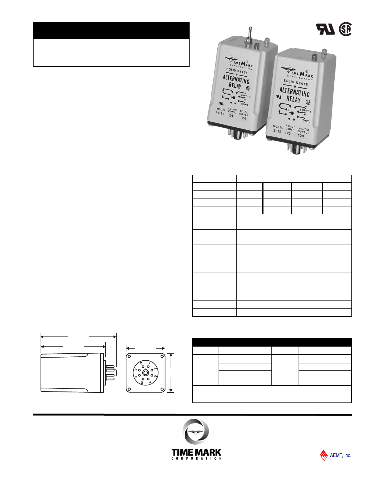
MODEL 261 series
3.77“
3.23“
1.95“
1.95“
TIME MARK is a division of
Alternating Relays
Solid-state Reliability
Heavy-duty Contact Rating
Optional Load 1-Load 2 Toggle
UL Recognized; CSA Certified
DESCRIPTION
The Model 261 series Alternating Relay is designed
for duplex pumping systems where it is desirable to
equalize pump run time. The solid state alternating
circuit drives an internal electromechanical relay. A
continuous power source and control switch are
required.
The control switch (float, pressure or other isolated
contact) is connected between the L1 terminal and the
control terminal. Each time the control switch is opened
the output contacts will change states. Indicator lights
on the case show the internal relay status.
On the optional toggle switch versions, the toggle switch
is set to the NORMAL position. Setting the switch to
Load 1 or Load 2 will lock the relay in position,
preventing alternation.
DIMENSIONS - 261S or 261DX
SPECIFICATIONS
MODEL 261 x (T) - xxx
Supply Voltage 12V AC/DC 24V AC/DC 120V AC/DC 240V AC/DC
Voltage Range 10 - 14V 20 - 28V 90 - 130V 180 - 250V
Max Voltage 15V 30V 140V 260V
Supply Current
Control Current
Operating Duty Continuous
Min. Cycle Time 100ms
Contacts 10A at 120VAC resistive
Expected Relay Life Mech: 10 million operations
Operating Temp 240V models: -20º to +131º F
Humidity Tolerance 0 - 97% w/o condensation
Mounting 261D: 11-pin socket *
Enclosure Material ABS plastic
Weight
Agency Approvals UL Recognized and CSA Certified
0.1A 0.05A 0.01A 0.01A
0.001A
Elec: 100,000 operations at rated load
All other models: -20º to +140º F
261S or 261DX: 8-pin socket **
4.3 oz.
*order 11-pin socket # 51X016
**order 8-pin socket # 51X120
*add 3/4” (0.75) for toggle clearance on applicable models
ORDERING INFORMATION
MODEL RELAY POLES TOGGLE SUPPLY VOLTAGE
261 S=single pole T 12V AC/DC
D=double pole 24V AC/DC
DX=dbl pole x-wired 120V AC/DC
240V AC/DC
example: 261-DX-120 orders a 120V AC/DC; double-pole,
x-wired Alternating Relay w/o the toggle option.
12/2012
© 2012 TIME MARK CORPORATION
Page 2
Control
Supply
SWITCH
Control
L1
L2
10
2
6
4
8
9
11
3
1
RL1
RL2
L2
L1
M1
M2
L 2
L 1
7
8
6
3
+
2
1
-
MODEL 261
TIME MARK is a division of
Alternating Relays
READ ALL INSTRUCTIONS BEFORE INSTALLING, OPERATING OR SERVICING THIS DEVICE.
KEEP THIS DATA SHEET FOR FUTURE REFERENCE.
GENERAL SAFETY
POTENTIALLY HAZARDOUS VOLTAGES ARE PRESENT AT THE TERMINALS OF THE MODEL 261.
ALL ELECTRICAL POWER SHOULD BE REMOVED WHEN CONNECTING OR DISCONNECTING WIRING.
THIS DEVICE SHOULD BE INSTALLED AND SERVICED BY QUALIFIED PERSONNEL.
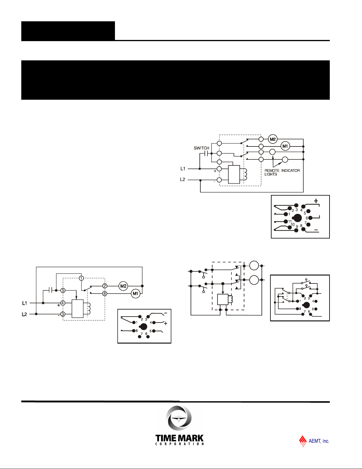
Installation Instructions
INSTALLATION
Connect wiring to the socket as indicated in the
following examples.
The Model 261 series Alternating Relays are extremely
versatile and can be used in many other configurations
besides those shown. Any type of switch (float,
pressure, etc.) can be used as the control switch;
however, it must be connected as shown (from L1 to the
control input) or the alternator will not function properly.
On Toggle Versions: For normal operation (alternating
loads) set the toggle switch on the top of the case to the
“normal” position. Setting the toggle switch to either “1”
or “2” will lock the alternator in that position.
TYPICAL APPLICATION: 261D
TYPICAL APPLICATION: 261S
NOTE: All drawings shown with no power applied.
TROUBLESHOOTING
Should the Model 261 fail to operate properly, check to
see that voltage level and connections are correct and
securely attached to equipment. Should problems
persist, contact the factory at 800-862-2875 for
assistance.
TYPICAL APPLICATION: 261DX
WARRANTY
This product is warranted to be free from defects in
materials and workmanship, and is covered by our
exclusive 5-year Unconditional Warranty. Should this
device fail to operate for any reason, we will repair it for
five years from the date of manufacture. For complete
warranty details, see the Terms and Conditions of Sales
page in the front section of the Time Mark catalog or
contact Time Mark at 1-800-862-2875.
12/2012
© 2012 TIME MARK CORPORATION
 Loading...