

Page 1
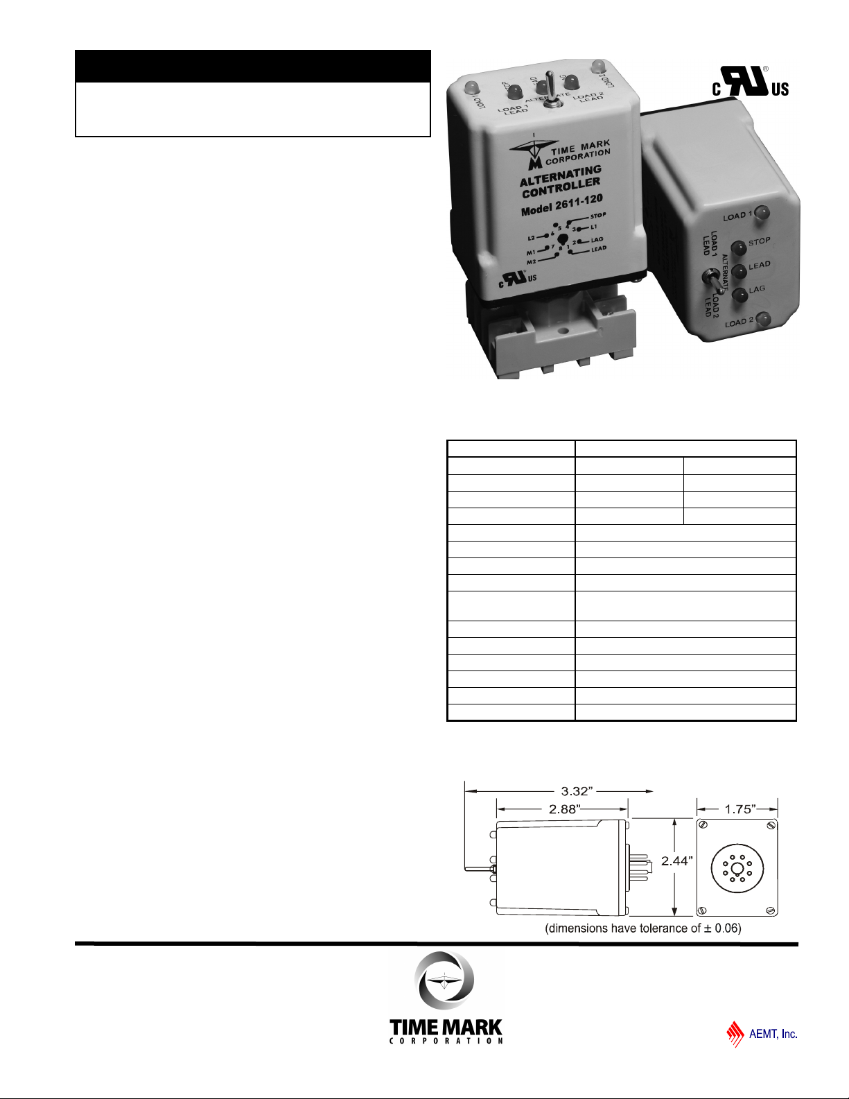
MODEL 2611
TIME MARK is a division of
Alternating Controller
Alternate Two Loads or Lock Sequence
with Lead Select Switch
Sequence On-Simultaneous off
(S.O.S.O.) Operation
Works with 3 Switches - STOP, LEAD & LAG
5 LEDs Indicate Switch and Relay Status
Control Switch Fault Detection
Replaces Multiple Components
Saving Space and Labor
DESCRIPTION
The Model 2611 Alternating Controller is a
microprocessor based controller designed for use
where two loads are required to alternate to provide
equal run time on the loads. LED indicators show the
status of the unit’s three control switch inputs and 2 load
outputs. A lead select switch allows the loads to
alternate normally in the center position, or disable
automatic sequencing and lock in a 1-2 or 2-1
sequence.
When a Stop, Lead or Lag switch closes, the
corresponding LED on top of the unit will illuminate.
When the Stop switch and Lead switch closes, Load 1
or Load 2 will come on and the corresponding green
LED will illuminate. If fluid levels continue to rise and
the Lag switch closes, the 2nd load will energize.
Loads remain energized until the Stop switch opens or
a fault condition is detected. See Typical Pump Down
Application - SOSO Operation on page 3 for details.
FAULT DETECTION
If any control switches open or close out of order, the
faulty switch is bypassed by the fault detection logic.
STOP, LEAD and LAG switch inputs are reassigned to
maintain safe operation. Should a faulty or fouled
switch begin operating normally, the fault detection logic
will restore STOP, LEAD and LAG assignments to their
proper designation.
SPECIFICATIONS
MODEL 2611
Supply Voltage 24V AC/DC 120V AC/DC
Voltage Range 20 - 28V 90 - 130V
Max Voltage 30V 140V
Supply Current
Control Current
Operating Duty Continuous
Min. Cycle Time 100ms
Contacts 10A at 120VAC resistive
Expected Relay Life
Operating Temp +32ºF to +140º F
Humidity Tolerance 0 - 97% w/o condensation
Mounting 8-pin socket*
Enclosure Material ABS plastic
Weight 4.3 oz.
Agency Approvals UL Recognized (U.S. & Canadian)
0.05A 0.01A
0.001 amp
Mech: 10 million operations
Elec: 100,000 operations at rated load
* Order with 8-Pin Socket 51X120
DIMENSIONS - Model 2611
Page 1 of 3 11/2011
© 2011 TIME MARK CORPORATION
Page 2
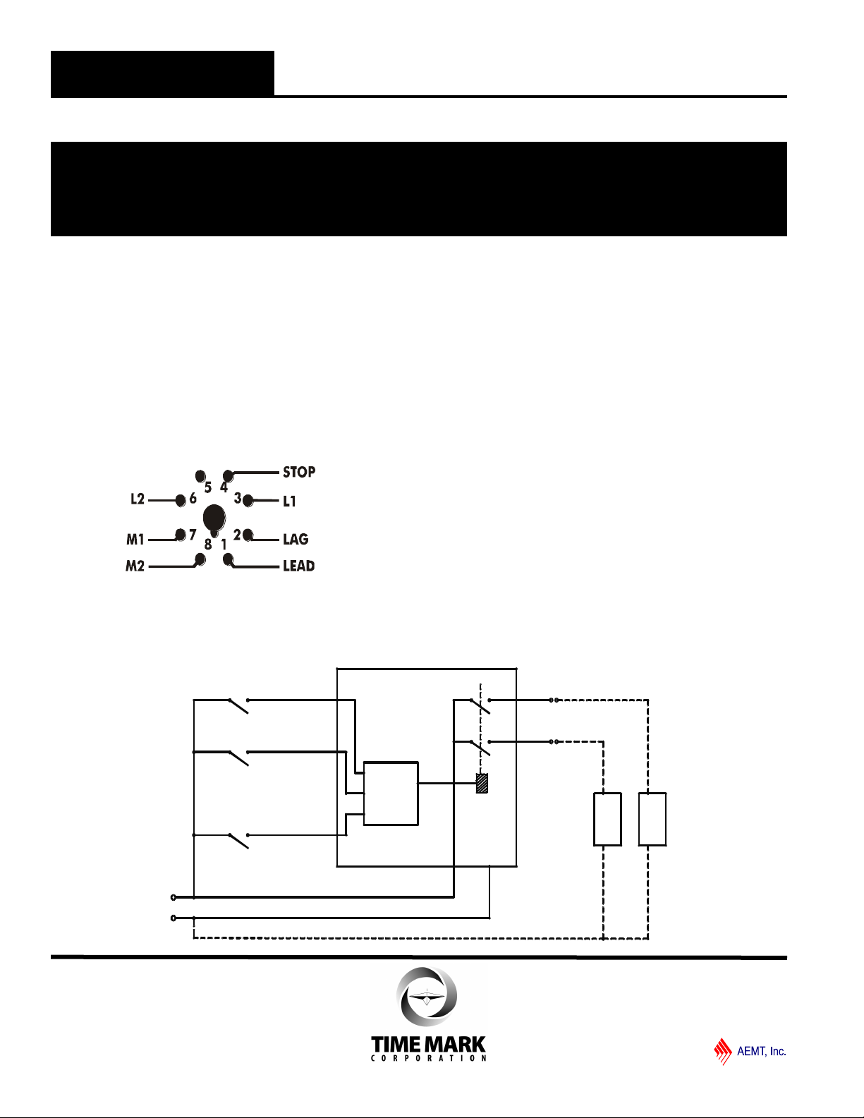
LAG
LEAD
STO P
MO D EL 2 611
2
1
4
LOA D CO M M O N TO L 2
3
6
8
7
M2
M1
L
O
A
D
1
L
O
A
D
2
uC
MODEL 2611
TIME MARK is a division of
Alternating Controller
READ ALL INSTRUCTIONS BEFORE INSTALLING, OPERATING OR SERVICING THIS DEVICE.
KEEP THIS DATA SHEET FOR FUTURE REFERENCE.
GENERAL SAFETY
POTENTIALLY HAZARDOUS VOLTAGES ARE PRESENT AT THE TERMINALS OF THE MODEL 2611.
ALL ELECTRICAL POWER SHOULD BE REMOVED WHEN CONNECTING OR DISCONNECTING WIRING.
THIS DEVICE SHOULD BE INSTALLED AND SERVICED BY QUALIFIED PERSONNEL.
INSTALLATION
Connect wiring to the socket as indicated in the
following examples.
The Model 2611 Alternating Controller is extremely
versatile and can be used in many other configurations
besides those shown. Any type of switches (float,
TROUBLESHOOTING
Should the Model 2611 fail to operate properly, check
to see that voltage level and connections are correct
and securely attached to equipment. Should problems
persist, contact the factory at 800-862-2875 for
assistance.
pressure, etc.) can be used as a control switch;
however, it must be connected as shown (from L1 to the
control input) or the alternator will not function properly.
WARRANTY
This product is warranted to be free from defects in
materials and workmanship, and is covered by our
exclusive 5-year Unconditional Warranty. Should this
device fail to operate for any reason, we will repair it for
five years from the date of manufacture. For complete
warranty details, see the Terms and Conditions of Sales
page in the front section of the Time Mark catalog or
contact Time Mark at 1-800-862-2875.
APPLICATION DIAGRAM - 2611
NOTE: All drawings shown with no power applied.
Page 2 of 3 11/2011
© 2011 TIME MARK CORPORATION
Page 3

EXTE RNAL REL AY
E-S TOP
ALA RM
L2
L1
NC
NO
LAG
LEA D
STO P
MO DEL 2 611
2
1
4
LOAD COMM ON TO L2
3
6
8
7
M2
M1
L
O
A
D
1
L
O
A
D
2
uC
MODEL 2611
EXTE RNAL R ELAY
E-S TOP
ALAR M
L2
L1
NC
NO
LAG
LEA D
STOP
MOD EL 261 1
2
1
4
LOAD COMM ON TO L2
3
6
8
7
M2
M1
L
O
A
D
1
L
O
A
D
2
uC
Alternating Controller Page 3 of 3 11/2011
TYPICAL PUMP DOWN APPLICATION - SOSO Operation
Step 1
In this example, the three normally open
dry float switches are designated Stop,
Lead and Lag. All switches begin open
and Load 1 and Load 2 are deenergized. The lead select switch
begins in the center (alternate) position.
Step 2
Fluid levels begin rising. STOP switch
closes, red STOP LED lights indicating
switch closure. No loads are
energized.
Step 3
Fluid levels continue to rise, LEAD
switch closes and energizes 1st load.
Red LED lights indicating LEAD switch
closure and a green LOAD 1 or LOAD 2
LED lights indicating which load is
currently LEAD.
Step 4
Fluid levels continue to rise, LAG switch
closes, energizes 2nd load, and lights
red LAG switch LED and remaining
green LOAD LED.
Step 5
As fluid levels fall, LEAD and LAG
switches open, loads remain energized
until the STOP switch opens. Red
switch status LEDs turn off as
corresponding switches open.
Step 6
Fluid levels fall below the STOP switch,
de-energizing all loads and turning off
green load status LEDs. Control logic
alternates LEAD load, unless automatic
sequencing is disabled by the Lead
Select switch.
OPTIONAL APPLICATION DIAGRAMS NOTE: All drawings shown with no power applied.
Using emergency STOP float switch (E-Stop) and SPDT relay to trigger alarm & cut power to LOAD 1 and LOAD 2.
As above, but wired with a high alarm float switch
Page 4

TIME MARK is a division of
Have Questions? Call us at (800) 862-2875 and talk to a real live person.
Main (918) 438-1220
11/2011
© 2011 TIME MARK CORPORATION
 Loading...