

Page 1
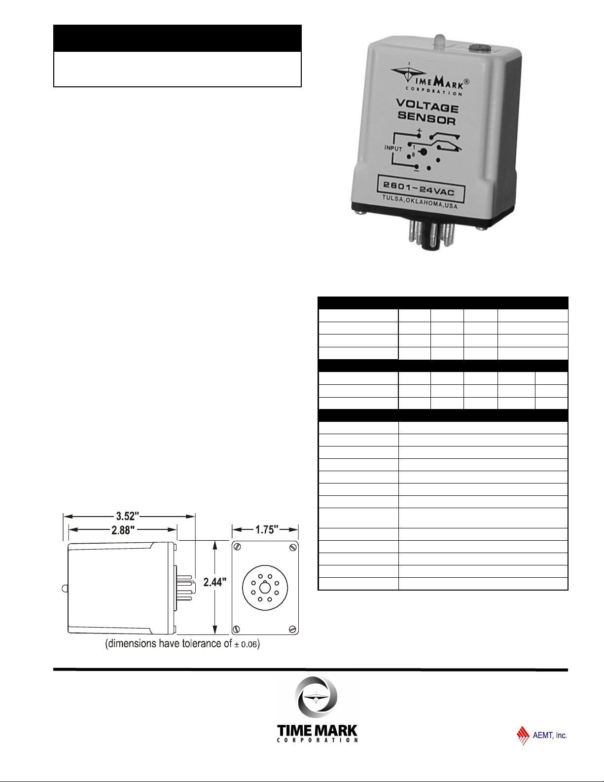
MODEL 2601
TIME MARK is a division of
Voltage Sensor
Monitors Under Voltage
SPDT Output
Automatic Reset
5 Year Unconditional Warranty
DESCRIPTION
The Model 2601 Voltage Sensor is a single-setpoint
under voltage monitor. Input voltages above the
setpoint will cause the output contact to energize and
the LED indicator to illuminate. Input voltages below the
setpoint will cause the output contact to de-energize
and the LED indicator will go off.
The 2601 Voltage Sensor is available in AC or DC
versions. AC models of the 2601 are not frequency
sensitive and can be used on systems from 50 to
400Hz. The voltage level is screwdriver adjustable over
a wide operating range.
This device requires a standard 8-pin socket for
mounting (see Model 51X120 under Accessories in the
Time Mark catalog).
DIMENSIONS
SPECIFICATIONS
2601 - AC VERSIONS
Nominal AC Voltages 24VAC 120VAC 208VAC 240VAC
Voltage Range 19 - 24 90 - 120 185 - 200 200 - 240
Max. Input Voltage 32V 160V 250V 285V
Input Frequency (Hz) 50 - 400 50 - 400 50 - 400 50 - 400
2601 - DC VERSIONS
Nominal DC Voltage 12VDC 24VDC 28VDC 48VDC 110VDC
Voltage Range 10 - 12 19 - 24 22 - 28 33 - 48 85 - 100
Max. Input Voltage 17V 32V 37V 62V 145V
2601 - ALL VERSIONS
Power Consumption 2W max.
Setpoint Stability ± 0.5% of setpoint
Dead Band 2% or less
Polarity Protection DC versions only
Trip Response 0.5 second fixed (± 0.1 second)
Reset Time 0.1 second
Output Contacts SPDT 10A at 240VAC resistive
Expected Relay Life Mech: 10 million operations
Elec: 100,000 at rated load
Operating Temp -20º to +122º F
Humidity Tolerance 97% w/o condensation
Mounting 8-pin socket *(order separately)
Enclosure Material ABS plastic
Weight 5 oz.
* Order 8-pin socket number 51X120
Sales (800) 862-2875
Main (918) 438-1220
10/2013
© 2013 TIME MARK CORPORATION
Page 2
MODEL 2601
TIME MARK is a division of
Voltage Sensor
READ ALL INSTRUCTIONS BEFORE INSTALLING, OPERATING OR SERVICING THIS DEVICE.
KEEP THIS DATA SHEET FOR FUTURE REFERENCE.
GENERAL SAFETY
POTENTIALLY HAZARDOUS VOLTAGES ARE PRESENT AT THE TERMINALS OF THE MODEL 2601.
ALL ELECTRICAL POWER SHOULD BE REMOVED WHEN CONNECTING OR DISCONNECTING WIRING.
THIS DEVICE SHOULD BE INSTALLED AND SERVICED BY QUALIFIED PERSONNEL.
Installation Instructions
INSTALLATION
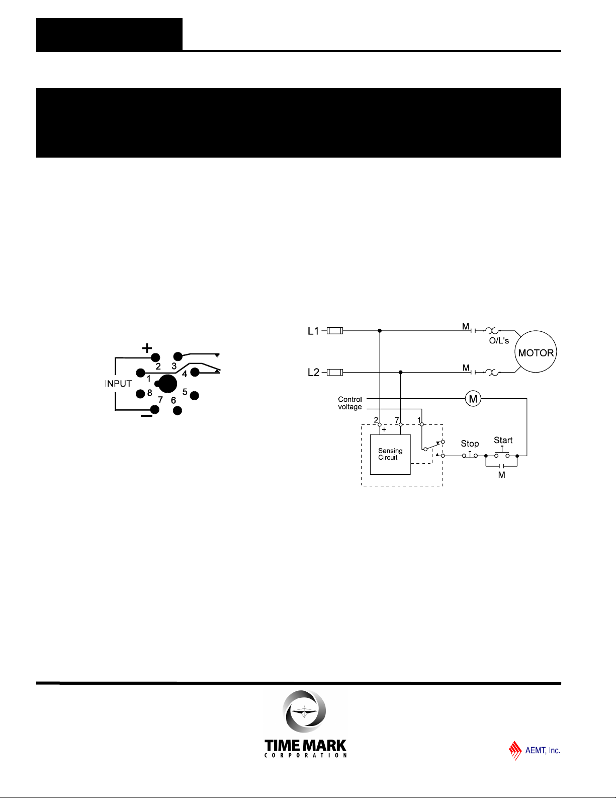
The Model 2601 is a socket-mounted voltage sensing
relay. The pin configuration diagram, below and on the
unit, shows the contacts in the power off or tripped
condition. Connect the wiring to the socket as shown in
the Typical Application Diagram. Observe the proper
polarity of the input voltage for DC models.
PIN DIAGRAM
ADJUSTMENT PROCEDURE
NOTE: When adjusting the Model 2601 you may wish
to jumper the control circuit contacts to prevent tripping
the load on and off. A variable voltage source and a
digital voltmeter provide the most accurate means of
calibrating the trip point.
For under voltage sensing, slowly rotate the
adjustment pot counter clockwise until the indicator
light just illuminates and the contacts transfer. Any
voltage below this level will now trip the relay.
A reasonably accurate voltage setting can be obtained
by using only the operating line voltage. Apply the
voltage and follow the adjustment procedure above.
Any voltage approximately 2% to 4% below the nominal
voltage will now trip the relay. To prevent nuisance
tripping you may need to turn the adjustments slightly
lower as needed.
NOTE: When installing the Model 2601 in areas of high
humidity or contamination, the base area and all exposed
metal parts of the socket should be coated with a good
quality silicone grease such as Dow Corning* DC-4 or DC-4x.
Insert the relay into the socket and wipe off excess grease
from around the base. This will help prevent moisture and
other contaminants from entering the base and socket areas.
TYPICAL APPLICATION
4
3
Model 2601
Shows No Power Applied
WARRANTY
This product is warranted to be free from defects in
materials and workmanship, and is covered by our
exclusive 5-year Unconditional Warranty. Should
this device fail to operate for any reason, we will repair
it for five years from the date of manufacture. For
complete warranty details, see the Terms and
Conditions of Sales page in the front section of the
Time Mark catalog or contact Time Mark at 1-800-862-
2875.
Sales (800) 862-2875
Main (918) 438-1220
10/2013
© 2013 TIME MARK CORPORATION
 Loading...