

Page 1

MODEL 260
TIME MAR K is a division of
Voltage Sensor
Monitors for Over or Under Voltage
LED status indicator
Plug-in Mounting
Automatic or Manual Reset
5 Year Unconditional Warranty
DESCRIPTION
The Model 260 Voltage Sensor is a single setpoint voltage
sensor. Input voltages above the setpoint cause the output
contacts to energize (contacts 1 & 8 closed). Input voltages
below the setpoint cause the output contacts to de-energize
(contacts 1 & 2 closed). The dead band between pull-in and
drop-out is less than 2%.
The standard unit has a screwdriver, or fingertip adjustable
setpoint range of approximately 35% of the maximum
voltage. This device can also be provided with a factory
calibrated trip point.
AC versions of the Model 260 Voltage Sensor are not
frequency sensitive, and may be used in systems from 50Hz
to 400Hz. DC models are not polarity sensitive.
This device requires a standard 8-pin socket, such as Time
Mark’s Model 51X120.
ORDERING STANDARD MODELS:
AUTOMATIC RESET
AC DC
AC260B-80-130 DC260B-20-24
#AC260B-90-150
AC260B-160-250 DC260B-42-64
AC260B-215-290 DC260B-60-92
AC260B-380-480 DC260B-90-150
#AC260B-400-560
MANUAL RESET
AC DC
AC260BM-80-130 DC260BM-20-24
#AC260BM-90-150
AC260BM-160-250 DC260BM-42-64
AC260BM-215-290 DC260BM-60-92
AC260BM-380-480 DC260BM-90-150
#AC260BM-400-560
DC260B-30-46
DC260B-160-250
#DC260B-250-350
DC260BM-30-46
DC260BM-160-250
#DC260BM-250-350
on most models
SPECIFICATIONS
MODEL 260
Input voltage see Ordering Info tables
Transient protection 2500 VRMS for 10ms
Polarity protection not required
Supply current 10mA max.
Setpoint stability ± 1%
Response time 100ms
Operation Continuous duty
Output contacts SPDT 10 Amps at 240VAC resistive
Expected relay life
Operating temperature -20º to +131º F
Humidity tolerance 0 - 97% without condensation
Enclosure material ABS plastic
Mounting 8-pin socket (**order separately)
Weight 5 oz.
Agency approval Most AC & DC Auto Reset versions:
ORDERING NON-STANDARD VERSIONS:
Voltage Model Adjustment Reset
DC 260 A=factory calibrated
AC
example: AC260 AM 230
orders an AC voltage sensor with manual reset, factory calibrated to trip at 230VAC
Mech: 10 million operations
Elec: 100,000 operations at rated load
UL Recognized* and CSA Certified*
* condition of acceptability:
must use a UL Recognized 600V socket, like
Time Mark’s 8-pin Model # 51X120.
# Exception:
M=manual reset
or auto reset
is assumed
B=screwdriver adjust
Units receiving input voltages of 300 volts or more
Models listed with # do not have agency approval
Setpoint
or Range
xxx or
xxx-xxx
Sales (800) 862-2875
Main (918) 438-1220
11/2011
© 2011 TIME MARK CORPORATION
Page 2
1.95"
MODEL 260
1
2 3
4
5
6
7
8
TIME MAR K is a division of
Voltage Sensor
READ ALL INSTRUCTIONS BEFORE INSTALLING, OPERATING OR SERVICING THIS DEVICE.
KEEP THIS DATA SHEET FOR FUTURE REFERENCE.
GENERAL SAFETY
POTENTIALLY HAZARDOUS VOLTAGES ARE PRESENT AT THE TERMINALS OF THE MODEL 260.
ALL ELECTRICAL POWER SHOULD BE REMOVED WHEN CONNECTING OR DISCONNECTING WIRING.
THIS DEVICE SHOULD BE INSTALLED AND SERVICED BY QUALIFIED PERSONNEL.
Installation Instructions
INSTALLATION
Mount the unit in a suitable enclosure. A NEMA-1 enclosure, designed
for socket-mounted relays is available from Time Mark.
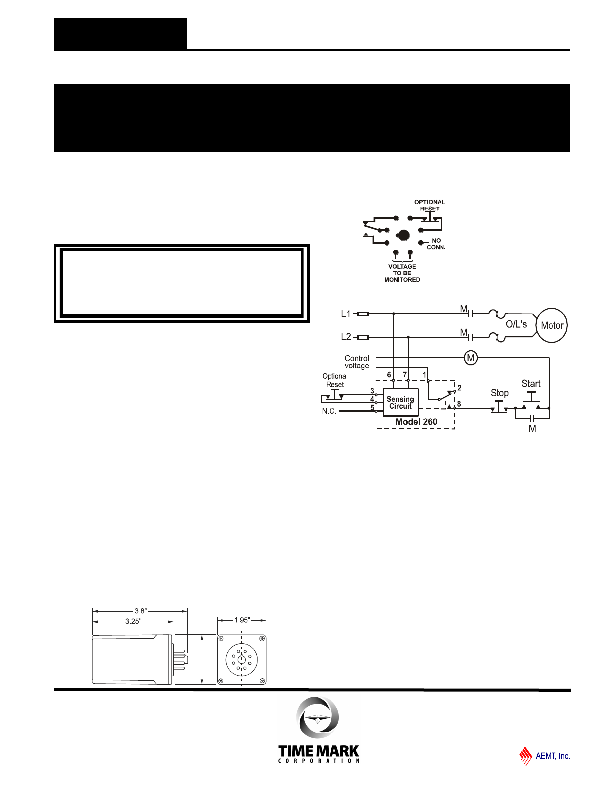
Connect the voltage to be monitored to terminals 6 and 7. These terminals are not polarity sensitive for any of the listed AC or DC models.
IN APPLICATIONS WHERE VOLTAGES IN EXCESS OF
300VAC ARE TO BE MONITORED, BE CERTAIN TO USE
THE TIME MARK MODEL 51X120 8-PIN SOCKET, OR AN
EQUIVALENT UL APPROVED 600VAC RATED SOCKET.
Connect the load control wiring to the appropriate terminals on the
socket:
For motor control applications; use terminals 1 and 8.
For phase loss alarm applications; use terminals 1 and 2.
Insert the Model 260 into the socket and apply power. If the contact
does not transfer (green light ON), use a voltmeter to insure that the
proper voltage is present. If voltage is correct, rotate the level
adjustment fully counter-clockwise. The contact should transfer to
provide a signal path between pins 1 and 8.
NOTE: When installing the Model 260 Sensor in areas of high humidity
or contamination, it is recommended that the base area and all
exposed metal parts of the socket be coated liberally with a good
quality silicone grease, such as Dow Corning DC-4 or DC-4X. Insert
the unit into the socket and wipe off excess grease around the base.
This will prevent the entrance of moisture and other contaminates into
the base and socket areas.
ADJUSTMENT PROCEDURE
The following procedure will allow the Model 260 Voltage Sensor to be
adjusted to achieve a trip point just below the nominal voltage being
monitored.
Rotate the adjustment control fully clockwise, or until the red (TRIP)
indicator illuminates.
On manual reset versions, it will be necessary to hold the reset button
down during this next step:
Slowly rotate the adjustment control in a counter-clockwise direction,
just until the green (NORM) indicator comes on.
WARNING
DIMENSIONS
PIN DIAGRAM
Shows contacts in power off condition
TYPICAL APPLICATION
Shows No Power Applied
At this point, the Model 260 Voltage Sensor is the most sensitive to
irregular power line conditions. If nuisance tripping occurs, turn the
control slightly farther counter-clockwise.
A more accurate setting will require the use of an adjustable voltage
source, and a voltmeter to achieve an exact setting.
TROUBLESHOOTING
Should the Model 260 Voltage Sensor fail to operate properly, check
that proper voltage is being applied to pins 6 and 7. On manual
reset versions, place a jumper across pins 3 and 4 if an external,
normally-closed reset switch is not connected. Should problems
persist, contact your local Time Mark Distributor, or the factory at 800
-862-2875 (Monday-Friday; 8 a.m. to 5 p.m. CST), for further
assistance.
WARRANTY
This product is warranted to be free from defects in materials and
workmanship, and is covered by our exclusive 5-year Unconditional
Warranty. Should this device fail to operate for any reason, we will
repair it for five years from the date of manufacture. For complete
warranty details, see the Terms and Conditions of Sales page in the
front section of the Time Mark catalog or contact Time Mark at 1-800-
862-2875.
Sales (800) 862-2875
Main (918) 438-1220
11/2011
© 2011 TIME MARK CORPORATION
 Loading...