

3.13"
3.5"
2.2"
4.0"
4.8"
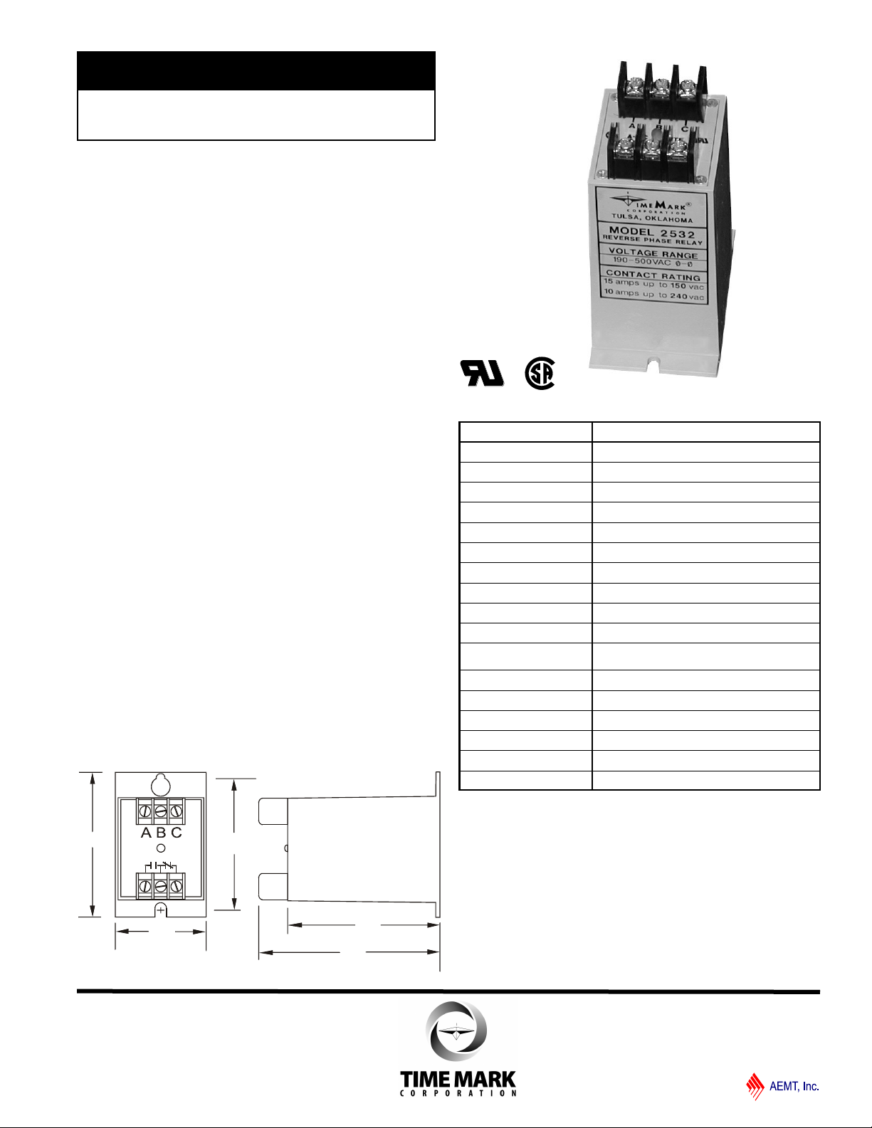
MODEL 2532
TIME MARK is a division of
Reverse Phase Relay
Senses phase reversal on Wye or Delta
190 to 500 VAC range
Machine tool case
UL Recognized & CSA Certified
DESCRIPTION
The Model 2532 Reverse Phase Relay is designed to
continuously monitor phase rotation of 3-phase lines.
This device should be used in applications where proper
phase rotation is critical, such as fan motors,
compressors, grinders, elevators, etc.
The solid-state sensing circuit drives an internal
electromechanical relay which energizes when power,
with correct phase rotation, is applied.
The relay will not energize if the applied phases are
reversed. It will de-energize if phase rotation is reversed
while the motor is running. An LED indicator will
illuminate with correct ABC phase rotation.
DIMENSIONS
SPECIFICATIONS
Model 2532
Nominal voltage 190-500 VAC (phase to phase)
Frequency 50 to 60Hz
Power Consumption 2W per phase
Transient protection 2500 VRMS for 10ms
Repeat accuracy
Response time
Reset time
Reset type Automatic
Dead band Approximately 2 %
Output contacts SPDT 10A at 240VAC resistive
Expected relay life Mechanical: 10 million operations
Electrical: 100,000 at rated load
Operating temp - 20º to +131º F
Humidity tolerance 0-97 % w/o condensation
Case material ABS plastic
Mounting Surface
Weight 7 oz.
Agency approval UL Recognized and CSA Certified
± 0.1 % (fixed conditions)
.05 seconds
.05 seconds
11/2011
© 2011 TIME MARK CORPORATION
A
B
NO NCC
C
MODEL 2532
TIME MARK is a division of
Reverse Phase Relay
READ ALL INSTRUCTIONS BEFORE INSTALLING, OPERATING OR SERVICING THIS DEVICE.
KEEP THIS DATA SHEET FOR FUTURE REFERENCE.
GENERAL SAFETY
POTENTIALLY HAZARDOUS VOLTAGES ARE PRESENT AT THE TERMINALS OF THE MODEL 2532.
ALL ELECTRICAL POWER SHOULD BE REMOVED WHEN CONNECTING OR DISCONNECTING WIRING.
THIS DEVICE SHOULD BE INSTALLED AND SERVICED BY QUALIFIED PERSONNEL.
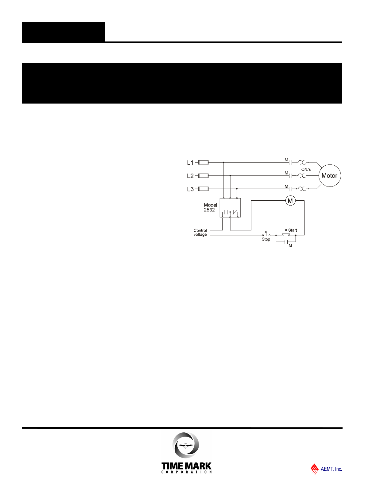
Installation Instructions
INSTALLATION
Mount the Model 2532 in the desired location.
Connect the 3-phase power to the terminals marked A,
B, and C.
Connect the control circuit to the terminals with the
contact markings. Refer to the Typical Application
wiring diagram for additional information.
If the relay contacts do not transfer when power is
applied (LED indicator-Off), check that all three
voltages are correct.
If power is present and the voltage is correct, remove
power. Reverse two of the three phase connections.
Re-apply power.
The contacts should transfer to the normal condition
(normally open contacts closed; LED indicator-On).
Calibrations or adjustments are not required.
TROUBLESHOOTING
Should the relay fail to operate properly, check that all
three voltages are present and are of the correct level.
Check all fuses and verify that all wiring connections are
correct. Should problems persist, contact the factory for
assistance.
TYPICAL APPLICATION
WARRANTY
This product is warranted to be free from defects in
materials and workmanship, and is covered by our
exclusive 5-year Unconditional Warranty. Should
this device fail to operate for any reason, we will repair
it for five years from the date of manufacture. For
complete warranty details, see the Terms and
Conditions of Sales page in the front section of the
Time Mark catalog or contact Time Mark at 1-800-862-
2875.
11/2011
© 2011 TIME MARK CORPORATION
 Loading...