

MODEL 2522
TIME MARK is a division of
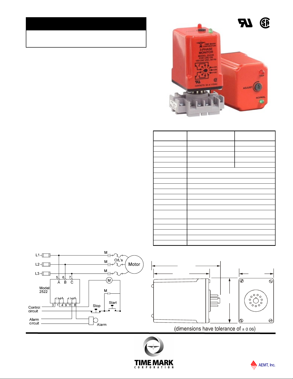
2.88”
2.44”
1.75”
3.52”
3-Phase Monitor
Detects Phase Loss, Low Voltage,
Phase Reversal
Automatic or Manual Reset
DPDT Relay Output
DESCRIPTION
The Model 2522 continuously monitors 3-phase power
lines for abnormal conditions. When properly adjusted, the
Model 2522 will detect phase loss on a loaded motor even
when regenerated voltage is present.
This unit consists of a solid-state voltage and phase-angle
sensing circuit, driving an electromechanical relay with
DPDT contacts. When correct voltage and phase rotation
are applied, the internal relay will energize. A fault
condition will de-energize the relay. When the fault is
corrected the Model 2522 will reset.
Both automatic and manual reset versions are available.
The Model 2522 does not require a neutral connection, and
can be used with Wye or Delta systems. Adjustment
ranges are sufficiently wide to allow for proper adjustment
to existing conditions. A failure indicator is provided to aid
in adjustment and system troubleshooting.
TYPICAL APPLICATION
SPECIFICATIONS
AUTO Reset
MANUAL Reset
Nominal Voltage 120VAC 208/240VAC
Max Input Voltage 132VAC 262VAC
Adjustment Range 85-120VAC 160-240VAC
Frequency 60Hz 60Hz
Power Consumption
Transient Protection 2500 VRMS for 10ms
Repeat Accuracy
Response Time
Reset Time
Reset Type Automatic or Manual
Dead Band 2%
Contact Rating DPDT 5 amps , 115VAC resistive
Max. Contact Rating 870 VA, 30VDC, 300VAC
Expected Relay Life Mech: 10 million operations
Elec: 100,000 operations at rated load
Operating Temp - 20º to +131º F
Humidity Tolerance 97% w/o condensation
Enclosure Material ABS plastic
Mounting *11-pin socket (order separately)
Weight 5 oz.
B2522B
B2522BM
.75W 1.5W
±0.1% of set-point (fixed conditions)
0.05 seconds
0.05 seconds
*Order socket number 51X016
2522B
2522BM
DIMENSIONS
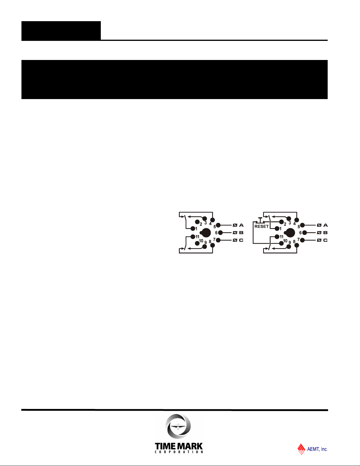
Shows No Power Applied
11/2011
© 2011 TIME MARK CORPORATION
MODEL 2522
TIME MARK is a division of
3-Phase Monitor
READ ALL INSTRUCTIONS BEFORE INSTALLING, OPERATING OR SERVICING THIS DEVICE.
KEEP THIS DATA SHEET FOR FUTURE REFERENCE.
GENERAL SAFETY
POTENTIALLY HAZARDOUS VOLTAGES ARE PRESENT AT THE TERMINALS OF THE MODEL 2522.
ALL ELECTRICAL POWER SHOULD BE REMOVED WHEN CONNECTING OR DISCONNECTING WIRING.
THIS DEVICE SHOULD BE INSTALLED AND SERVICED BY QUALIFIED PERSONNEL.
Installation Instructions
INSTALLATION
Mount the 11-pin socket in a suitable enclosure.
Connect 3-phase power to terminals 5, 6 and 7 on the
socket. Phase rotation may be verified using a Time Mark
Model 108A or 108B Phase Sequence Detector.
Connect the load control wiring to the appropriate
terminals on the socket:
For motor control applications; use terminals 1 and 3.
For phase loss alarm applications; use terminals 11 and 8.
Insert the Model 2522 into the socket and apply power.
If the contacts do not transfer, (green light ON), check that
all phases are present and of the correct voltage. If power
is correct, rotate the level adjustment counter-clockwise
(CCW). If the contact still does not transfer, remove
power and reverse any two of the three phase wires at the
socket (phase rotation is reversed).
Re-apply power. The contact should transfer to provide a
signal path between pins 1 and 3 and pins 9 and 11. The
green LED should be lit.
NOTE: When installing the Model 2522 monitor in areas of
high humidity or contamination, it is recommended that the
base area and all exposed metal parts of the socket be
coated liberally with a good quality silicone grease, such as
Dow Corning DC-4 or DC-4X. Insert the unit into the socket
and wipe off excess grease around the base. This will
prevent the entrance of moisture and other contaminates into
the base and socket areas.
ADJUSTMENT SETTINGS
The following procedure will allow the Model 2522 to be
adjusted to achieve a trip point just below the nominal
phase-to-phase voltage, where the unit is applied. On
manual reset versions, hold the reset button down
during the following procedure.
Rotate the adjustment control fully clockwise, or until the
red (TRIP) indicator illuminates.
Slowly rotate the adjustment control in a counter clockwise direction, just until the green (NORM) indicator
illuminates.
At this point, the Model 2522 is the most sensitive to
irregular power line conditions. If nuisance tripping
occurs, turn the control slightly farther counter-clockwise.
A more accurate setting will require the use of a 3-phase
variac to lower the voltage to an exact measurable setting.
Time Mark offers a factory set versions of all models and
voltage ranges, for only a small additional charge.
PIN DIAGRAMS
Automatic Reset Manual Reset
TROUBLESHOOTING
Should the Model 2522 fail to operate properly, check that
all three voltages are present and are of the correct
voltage level and phase rotation (a Model 108A or 108B
phase sequence detector may be used to verify phase
rotation). Check all fuses and verify that all wiring
connections are correct. If problems persist, contact your
local Time Mark Distributor, or the manufacturer at 800-
862-2875.
WARRANTY
This product is warranted to be free from defects in
materials and workmanship, and is covered by our
exclusive 5-year Unconditional Warranty. Should this
device fail to operate for any reason, we will repair it for
five years from the date of manufacture. For complete
warranty details, see the Terms and Conditions of Sales
page in the front section of the Time Mark catalog or
contact Time Mark at 1-800-862-2875.
11/2011
© 2011 TIME MARK CORPORATION
 Loading...