

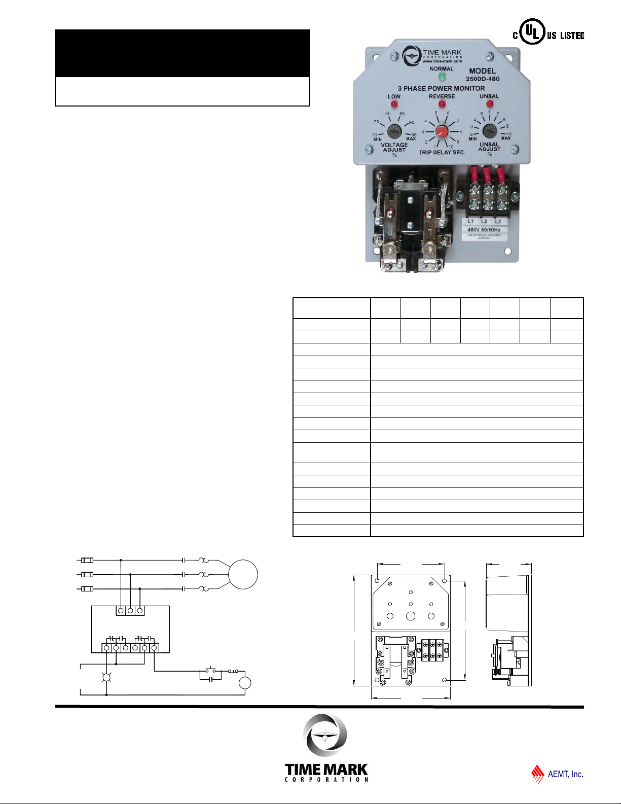
MODEL 2500D
TIME MARK is a division of
M
M
CONTROL
VOLTAGE
START STOP
FAULT
INDICATOR
MOTOR
L1
L2
L3
M
M
M
O/L's
TYPICAL APPLICATION
MOTOR PROTECTION
L1 L2
L3
MODEL 2501D
5.00"
7.00"
4.25"
6.25"
2.85"
MODEL 2501D
3-Phase Monitor
⚫ Monitors for Phase Loss or Reversal,
Low Voltage or Voltage Unbalance
⚫ Automatic Reset
⚫ Heavy Duty DPDT Output Contacts
⚫ UL Listed to U.S. and Canadian
Safety Standards
DESCRIPTION
The Models 2500D and 2501D 3-Phase Monitors are
designed to continuously monitor the voltages of a 3-phase
power distribution system for abnormal conditions. The
monitors feature solid-state voltage and phase angle
sensing circuits which drive a DPDT electromechanical
output relay. A neutral connection is not required with either
the Model 2500D or 2501D. This allows each model to be
connected to any three phase WYE or DELTA configured
power distribution system.
When the correct voltage and phase sequence is applied to
a specified Model 2500D, the output relay will not
energize. An under voltage, phase reversal, phase
unbalance or phase loss condition will cause the output
relay to energize, even if regenerated voltage is present.
Complete power loss will not cause Model 2500D to trip.
When the correct voltage and phase sequence is applied to
a specified Model 2501D, the output relay will energize. An
under voltage, phase reversal, phase unbalance, or phase
loss condition will cause the output relay to de-energize.
Each option on the Model 2500D or 2501D is adjustable
throughout its operating range. The adjustment pots and
LED indicators for VOLTAGE ADJUST, UNBALANCE
ADJUST and TIME DELAY are mounted on the front of the
unit, for easy access.
Seven versions of both the Model 2500D and the Model
2501D cover voltage ranges from 120 to 600 VAC. All
models are UL Listed to U.S. and Canadian safety
standards.
SPECIFICATIONS
Model 2500D-XXX
Model 2501D-XXX
Nominal AC Voltage 120 208 240 380 415 480 600
Adjustment Range
Frequency 50/60Hz
Unbal. adj range 2 to 10% per NEMA specifications
Trip Delay adj range 1 to 10 seconds (1 second increments)
Power Consumption 4.5W per phase
Repeat Accuracy ± 1% of full scale
Reset Time 150ms nominal
Reset Type Automatic
Dead Band 2% of full scale
Output Contacts DPDT 40 amps at 28VDC/300VAC 50/60Hz
Operating Temp - 4º to +131º F
Humidity Tolerance 0-97% without condensation
Enclosure Material ABS plastic
Weight 2 lbs. 5 oz.
Mounting Surface
Agency Approval UL Listed to U.S. and Canadian safety standards
-120 -208 -240 -380 -415 -480 -600
84-114V 146-198V 168-229V 266-361V 290-394V 336-456V 420-570V
5 amps at 480/600VAC 50/60Hz
TYPICAL APPLICATION - Motor Protection
DIMENSIONS
11440 Eas t Pi n e S t ree t
Tul s a, O kla h oma 74 1 16
08/18
© 2018 TIME MARK CORPORATION
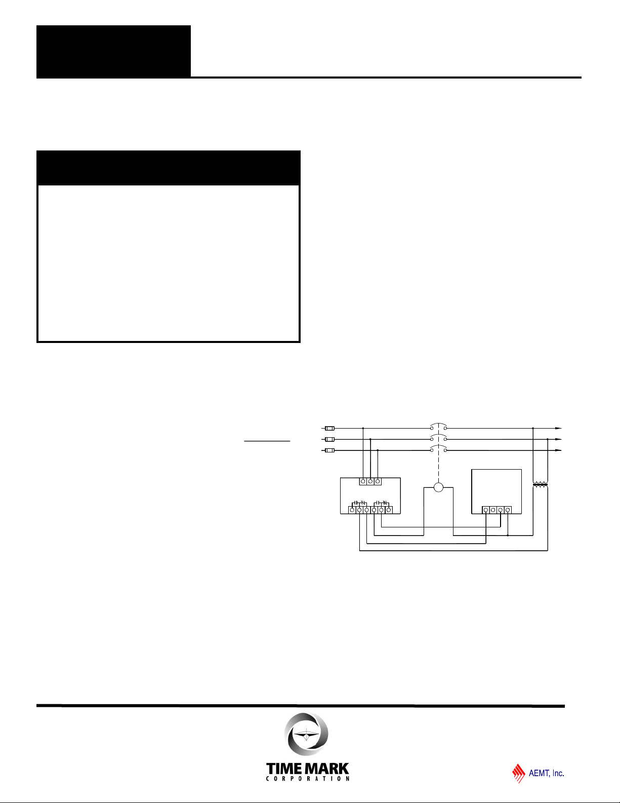
MODEL 2500D
TIME MARK is a division of
SHUNT
TRIP
BREAKER
L1
L2
L3
L1 L2
L3
MODEL 2500D
TYPICAL APPLICATION
SHUNT BREAKER WITH CAP TRIP DEVICE
DIAGRAM SHOWS NO POWER APPLIED
M
CAPACITOR
TRIP
DEVICE
MODEL 295
1 2
3
4
MODEL 2501D
READ ALL INSTRUCTIONS BEFORE INSTALLING, OPERATING OR SERVICING THIS DEVICE.
D A N G E R
• HAZARD OF ELECTRIC SHOCK, BURN OR
EXPLOSION
• POWER CONTROL & INSTRUMENT CIRCUITS MAY
BE SUPPLIED BY REMOTE SOURCES
• THIS DEVICE SHOULD ONLY BE INSTALLED OR
SERVICED BY QUALIFIED PERSONNEL
• TURN OFF ALL POWER SUPPLYING THIS DEVICE
BEFORE WORKING ON MONITOR
• FAILURE TO DO SO WILL RESULT IN DEATH OR
SEVERE PERSONAL INJURY
INSTALLATION
Mount the Model 2500D or 2501D in a stable location,
observing all precautions outlined in the statement
above. Mounting hardware is not included.
Connect the control wiring to the terminals with the
contact markings (refer to the diagram on the unit).
Markings shown on the unit are in the power off
condition. Apply power.
If the contacts transfer (NORMAL indicator-Off), check
the LOW, REVERSE, and UNBALANCE indicators for a
possible fault condition. If no indicators are lit, check
that all three phases are present and of the correct
voltage.
If all phases are correct and the LOW indicator is ON,
rotate the VOLTAGE ADJUST until the light just goes
out.
If the UNBAL indicator is ON, rotate the UNBAL
ADJUST until the light just goes out.
NOTE: During adjustment you may find the UNBAL
ADJUST and the TRIP DELAY adjustment has no
effect. Check for phase loss.
If the REVERSE indicator is ON, remove power and
reverse any two of the three input wires and re-apply
power. The NORMAL indicator will light.
3-Phase Monitor
KEEP THIS DATA SHEET FOR FUTURE REFERENCE.
Installation Instructions
ADJUSTMENT
Note: During adjustment, you may want to install a
jumper across the control contacts or open circuit,
depending on your control configuration, to prevent
cycling the load on and off.
Rotate the VOLTAGE ADJUST to the desired percent of
nominal voltage, or slowly clockwise, until the contacts
transfer to the failed condition (LOW indicator-ON).
Slowly turn the adjustment counter-clockwise until the
contacts reset to the normal condition (LOW indicator-OFF;
NORMAL indicator-ON).
Remove the jumper from the control contacts, if installed.
This setting will be correct for most applications. If nuisance
tripping occurs, turn the VOLTAGE ADJUST slightly counterclockwise, or increase the trip delay time.
Any adjustments to the VOLTAGE ADJUST, to eliminate
nuisance tripping, should be made in small increments, until
the true nuisance trips are eliminated. Adjust the TRIP
DELAY and UNBAL ADJUST as required by the system.
TYPICAL APPLICATION - Shunt Breaker
WARRANTY
This product is warranted to be free from defects in
materials and workmanship, and is covered by our exclusive
5-year Unconditional Warranty. Should this device fail to
operate for any reason, we will repair it for five years from
the date of manufacture. For complete warranty details, see
the Terms and Conditions of Sales page in the front section
of the Time Mark catalog or contact Time Mark at
1-800-862-2875.
11440 Eas t Pi n e S t ree t
Tul s a, O kla h oma 74 1 16
© 2018 TIME MARK CORPORATION
08/18
 Loading...