

Page 1
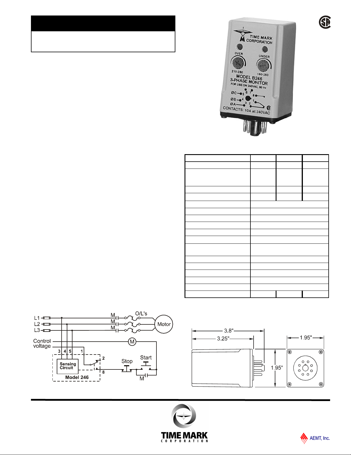
MODEL 246
TIME MARK is a division of
3-Phase Monitor
Monitors for Phase Loss or
Reversal, Low and Over Voltage
Automatic Reset
CSA Certified
5 Year Unconditional Warranty
DESCRIPTION
The Model 246 3-Phase Monitor is designed to
continuously monitor 3-phase power lines for phase
loss, phase reversal, low voltage and high voltage. This
device features solid-state voltage and phase angle
sensing circuits, which drive a SPDT electromechanical
relay. A neutral is not required, allowing the Model 246
to be used with either Wye or Delta systems.
Three versions of the Model 246 cover the 120 and
208/240VAC, 60Hz and the 380VAC, 50Hz. In addition,
the models A246 and B246 are now CSA Certified.
Each option on the Model 246 monitor is adjustable
throughout its operating range. The adjustment pots
and LED indicators for OVER VOLTAGE and UNDER
VOLTAGE are mounted on the front of the unit for easy
access.
TYPICAL APPLICATION
SPECIFICATIONS
Model A246 B246 EX246
Nominal AC Voltage 120 208/240 380
Adjustment Range
Low:
High:
Frequency 60Hz 60Hz 50Hz
Power Consumption (per phase) 1W
Transient Protection 2500V for 10ms
Repeat Accuracy
Response/Reset Time 50ms
Reset type Automatic
Dead Band 2%
Contact Rating SPDT 10A at 240VAC resistive
Expected Relay Life Mech: 10 million operations
Operating Temperature - 20º to +131º F
Humidity Tolerance 0-97% w/o condensation
Enclosure Material ABS plastic
Weight 6 oz.
Mounting 8-pin socket *order separately
Agency approval CSA CSA
85-125 V
110-140 V
±0.1% of set point (fixed conditions)
Elec: 100,000 at rated load
* Order 8-pin socket number 51X120
160-260 V
210-280 V
1.5W
300-400 V
350-450 V
2W
DIMENSIONS
Shows No Power Applied
11/2011
© 2011 TIME MARK CORPORATION
Page 2
MODEL 246
TIME MARK is a division of
3-Phase Monitor
READ ALL INSTRUCTIONS BEFORE INSTALLING, OPERATING OR SERVICING THIS DEVICE.
KEEP THIS DATA SHEET FOR FUTURE REFERENCE.
GENERAL SAFETY
POTENTIALLY HAZARDOUS VOLTAGES ARE PRESENT AT THE TERMINALS OF THE MODEL 246.
ALL ELECTRICAL POWER SHOULD BE REMOVED WHEN CONNECTING OR DISCONNECTING WIRING.
THIS DEVICE SHOULD BE INSTALLED AND SERVICED BY QUALIFIED PERSONNEL.
Installation Instructions
ADJUSTMENT PROCEDURE
WARNING
The Model 246 is not to be used with input
voltages greater than those for which the unit was
designed.
140VAC for Model A246
280VAC for Model B246
450VAC for Model EX246
INSTALLATION
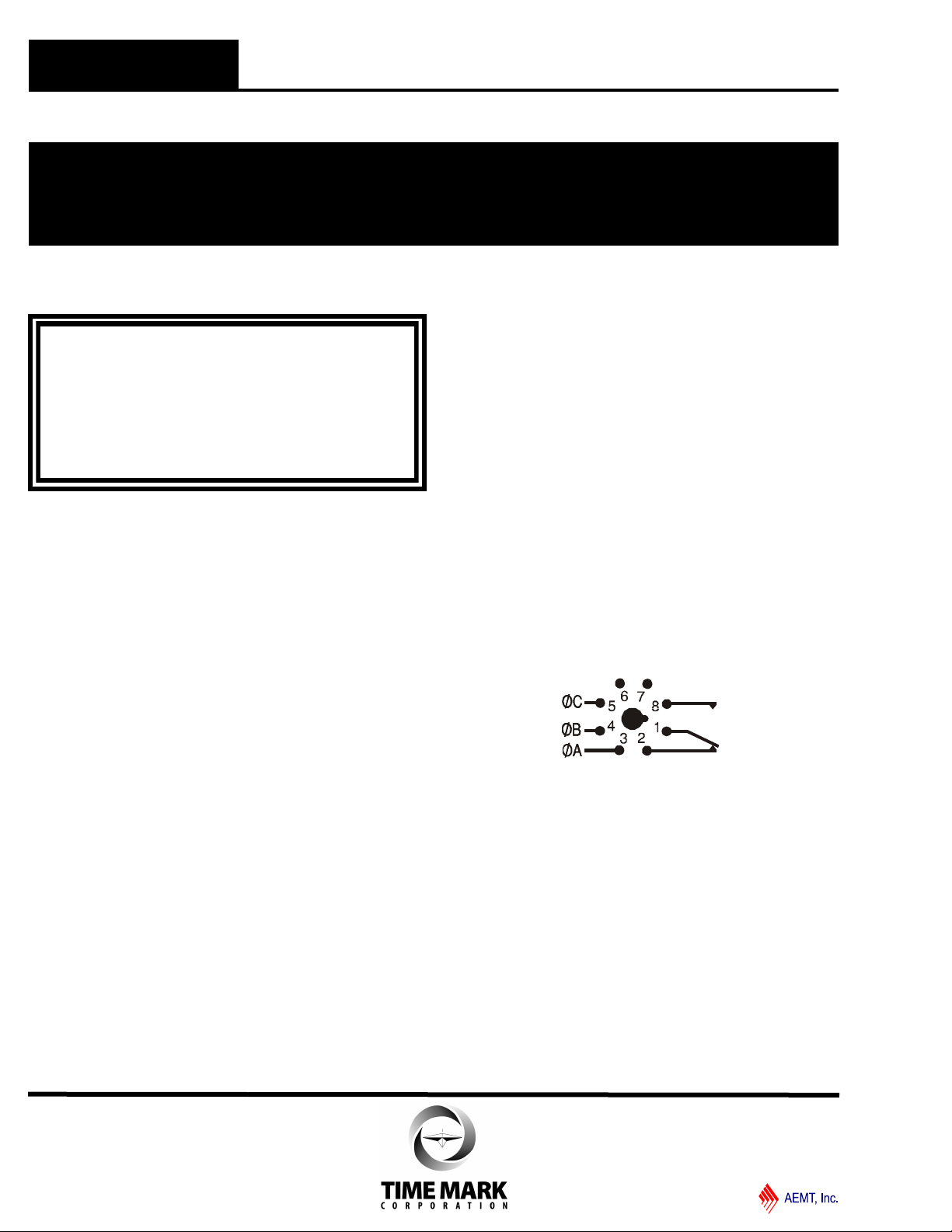
Connect the input power to the 8-pin socket, following
the Model 246 pin diagram, pictured on the unit, and on
this data sheet. Insert the Model 246 into the socket
and apply power.
If the contacts do not transfer (both LEDs-off), check
that all three phases are present and of the correct
voltage. If power is correct, rotate the UNDER
VOLTAGE adjustment counter-clockwise, and the
OVER VOLTAGE adjustment clockwise, to widen the
operating band.
If the contacts still do not transfer, remove power and
reverse two of the three phase wires, at the socket
(phase rotation is reversed). Re-apply the power. The
contacts should transfer to provide a signal path
between pins 1 & 8 (both LEDs-off).
NOTE: When installing the Model 246 Monitor in
areas of high humidity or contamination, it is
recommended that the base area and all exposed metal
parts of the socket be coated liberally with a good
quality silicone grease, such as Dow Corning DC-4 or
DC-4X. Insert the unit into the socket and wipe off
excess grease around the base. This will prevent the
entrance of moisture and other contaminates into the
base and socket areas.
Set UNDER VOLTAGE level: Rotate the UNDER
VOLTAGE adjustment pot clockwise, until the contacts
transfer (UNDER VOLTAGE LED-On). Slowly turn the
UNDER VOLTAGE adjustment counter-clockwise until the
contacts reset (UNDER VOLTAGE LED-Off).
Set OVER VOLTAGE level: Turn the OVER VOLTAGE
adjustment pot counter-clockwise, until the contacts
transfer (OVER VOLTAGE LED-On). Slowly turn the
OVER VOLTAGE adjustment pot clockwise until the
contacts reset (OVER VOLTAGE LED-Off).
Nuisance tripping: The settings achieved by these adjustments (above), will be correct for most applications.
Should nuisance tripping occur, turn the OVER VOLTAGE
and the UNDER VOLTAGE adjustments slightly further,
widening the operating band.
PIN DIAGRAM
TROUBLESHOOTING
Should the Model 246 3-Phase Monitor fail to operate,
check all connections. Verify that all three voltages are
present, and check all fuses. Should problems persist,
contact the factory for assistance.
WARRANTY
This product is warranted to be free from defects in
materials and workmanship, and is covered by our
exclusive 5-year Unconditional Warranty. Should this
device fail to operate for any reason, we will repair it for
five years from the date of manufacture. For complete
warranty details, see the Terms and Conditions of Sales
page in the front section of the Time Mark catalog or
contact Time Mark at 1-800-862-2875.
11/2011
© 2011 TIME MARK CORPORATION
 Loading...