

Page 1
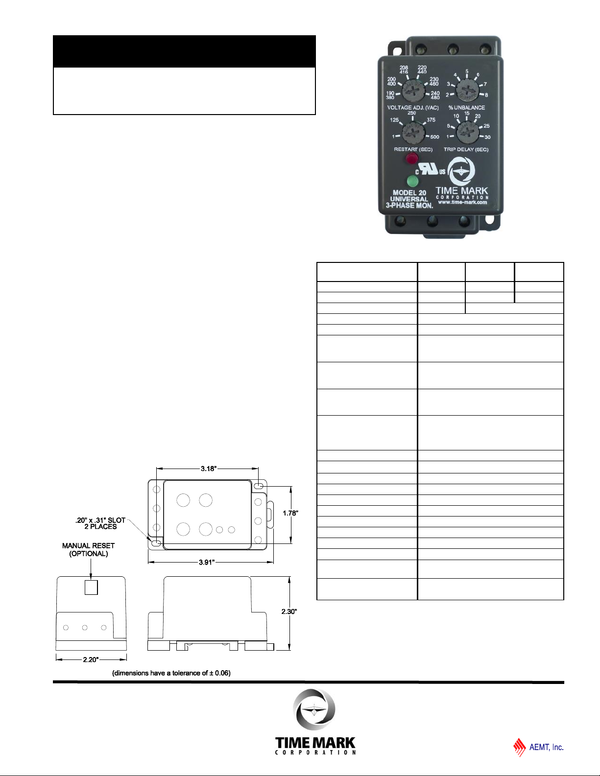
MODEL 20
TIME MARK is a division of
3-Phase Monitor
with Adjustable Trip & Restart Delays
⚫ Monitors for Phase Loss, Phase Reversal,
Over/Under Voltage and Voltage Unbalance
⚫ Three Voltage Options
⚫ LED Status Indicators
⚫ DIN Rail or Surface Mount
⚫ UL Recognized in the U.S. and Canada
DESCRIPTION
The Model 20 is a microcontroller-based universal 3-phase
monitor for protecting 3-phase motors from abnormal power
conditions. It can detect under voltage, over voltage, voltage
unbalance, reverse phase, and single-phasing even when
regenerated voltage is present. The Model 20 includes
adjustable trip and restart delays to prevent nuisance tripping
during power fluctuations and short cycling in compressor
applications. The LED status indicators and adjustment pots
for Voltage Adjustment, % Unbalance, Restart Delay and Trip
Delay are mounted on the front of the unit for easy access.
The Model 20 is UL Recognized in the U.S. and Canada.
Automatic or manual restart versions are available. The
Model 20 does not require a neutral connection and can be
used on either Wye or Delta systems.
All versions of the Model 20 are available with optional gold
flashed silver contacts for low current applications.
DIMENSIONS
SPECIFICATIONS
Auto Reset Models
Manual Reset Models*
Operating Voltage 190-480 VAC 95-120 VAC 475-600 VAC
Power Consumption 3.7W at 480V 3.7W at 120V 4.5W at 600V
Auto Ranges Yes No
Frequency 50/60Hz
Type of Measurement RMS
Under Voltage
Trip
Reset
Over Voltage
Trip
Reset
Voltage Unbalance
Trip
Reset
Trip Delay Time
Over, Under, & Unbalanced
Single-Phasing Faults
Unbalance > 15%
Restart Delay 1-500 sec., adjustable
Manual Reset Input 5V open circuit/500µA short circuit
Output Contacts SPDT 10 amps at 240VAC resistive
Operating Temp - 20º to +140º F
Humidity Tolerance 0-97% w/o condensation
Terminal Torque 3.5 in. lbs. maximum
Wire Type Stranded or solid 14-26 AWG, 1/terminal
Enclosure Noryl plastic
Mounting DIN Rail or Surface Mount
Weight 11 oz.
Option for Low Current
Applications
Agency Approval
20
20M
Trip setting minus 0.7%
Models ordered with suffix “/SG”
have silver with gold flash contacts
UL Recognized (U.S. and Canada)
(For use in a Polluon Degree 2 Environment)
20-L
20-LM
(% of setpoint)
90% ±1%
93% ±1%
(% of setpoint)
110% ±1%
107% ±1%
(conforms to NEMA)
2-8%, adjustable
1-30 sec., adjustable
1 sec., fixed
1 sec., fixed
20-H
20-HM
* External N.O. momentary pushbutton required for manual reset.
11440 East P i n e Stre e t
Tuls a , O k lahoma 7 4 1 16
06/2020
© 2019 TIME MARK CORPORATION
Page 2
MODEL 20
TIME MARK is a division of
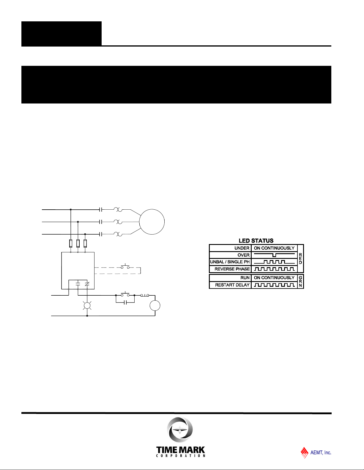
MOTOR
BA C
MODEL 20
L1
L2
L3
M
M
M
M
M
CONTROL
VOLTAGE
O/L's
START STOP
ALARM
INDICATOR
1 2
3
4
5 6
Manual Reset
(Model 20M)
FUSE: 1A 600VAC
RECOMENDED
Universal 3-Phase Monitor
READ ALL INSTRUCTIONS BEFORE INSTALLING, OPERATING OR SERVICING THIS DEVICE.
KEEP THIS DATA SHEET FOR FUTURE REFERENCE.
GENERAL SAFETY
POTENTIALLY HAZARDOUS VOLTAGES ARE PRESENT AT THE TERMINALS OF THE MODEL 20.
ALL ELECTRICAL POWER SHOULD BE REMOVED WHEN CONNECTING OR DISCONNECTING WIRING.
THIS DEVICE SHOULD BE INSTALLED AND SERVICED BY QUALIFIED PERSONNEL.
Installation Instructions
INSTALLATION
Mount the Model 20 in a suitable enclosure either to the back
panel of the enclosure using two #6 x 9/16" screws (not
included) or to a DIN rail.
Connect terminals A, B, and C to the line side of the motor
starter. Connect the output relay to the control circuit. When
using manual reset versions either connect a N.O. momentary
switch to the manual reset input for manual reset operation or
jumper the manual reset input for automatic reset operation.
Refer to wiring diagram for example of typical application.
OPERATION (Cont’d)
Manual Reset Versions
When operating in manual reset mode the restart delay is
disabled and the monitor must always be reset manually after
applying power. Both status lights will blink in unison upon
applying power if the monitor was not in the tripped state prior
to a loss of power.
If a fault condition is detected and the monitor trips, the relay
will remain de-energized until the fault condition clears and
the reset switch is pushed. If the monitor remains in the
tripped state when a loss of power occurs, the fault causing
the trip will be displayed on power up.
Automatic and Manual Reset Versions
The status of the 3-phase system is indicated by the red and
green LEDs as follows:
OPERATION
Set the VOLTAGE adjustment to the nominal operating
voltage. Models 20 and 20M will auto-range to either the 190240VAC or 380-480VAC scale. Set the UNBALANCE,
RESTART, and TRIP adjustments as required for the
application.
Automatic Reset Versions
The relay contacts will transfer after applying correct voltage
and phase rotation for the length of the restart delay. The
green LED will blink during the restart delay and will then
remain on indicating the relay contacts have transferred.
TROUBLESHOOTING
Should the Model 20 Monitor fail to operate properly, check
that all three voltages are present, and are of the correct
voltage level and phase rotation (a Model 108A or 108B
Phase Sequence Detector should be used to verify phase
rotation). Check all fuses and verify that all wiring connections
are correct. If problems persist, contact your local Time Mark
Distributor, or the factory for assistance (Monday-Friday, 8
a.m. to 5 p.m. CST).
WARRANTY
This product is warranted to be free from defects in materials
and workmanship, and is covered by our exclusive 5-year
Unconditional Warranty. Should this device fail to operate
for any reason, we will repair it for five years from the date of
manufacture. For complete warranty details, see the Terms
and Conditions of Sales page in the front section of the Time
Mark catalog or contact Time Mark at 1-800-862-2875.
11440 East P i n e Stre e t
Tuls a , O k lahoma 7 4 1 16
© 2019 TIME MARK CORPORATION
06/2020
 Loading...