

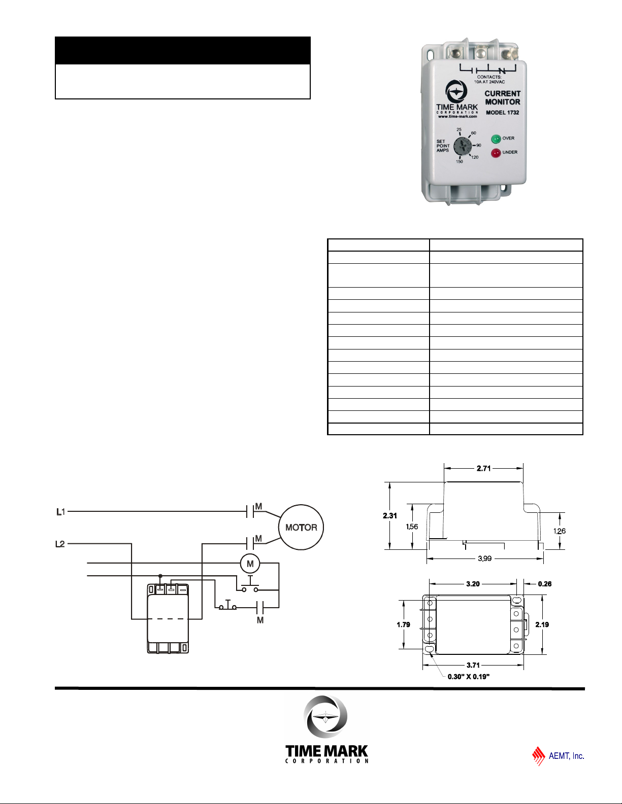
MODEL 1732
TIME MARK is a division of
NO NCC
Control
Voltage
SHOWN WITHOUT
APPLIED POWER
STOP
START
AC Current Monitor
⚫ Detects Over or Under Current
⚫ Adjustable Setpoint
⚫ No External Power Supply
⚫ Dual LED Condition Indicators
⚫ Surface or DIN Rail Mounting
DESCRIPTION
The Model 1732 AC Current Monitor is a single
setpoint current monitor. It can be used to detect either
over current or under current, depending on whether the
trip point is set above or below the input current. Dual
LED indicators on the front or top of the unit give a clear
visual reference for a fault condition.
The Model 1732 generates its operating voltage from
the monitored current line, so no external power supply
is required. A current greater than 25 amps is needed
to energize the internal relay. The maximum current set
point is 150 amps.
The Model 1732 is not frequency sensitive, and can be
used on AC currents from 50 to 400Hz. The compact
housing can be surface or DIN rail mounted.
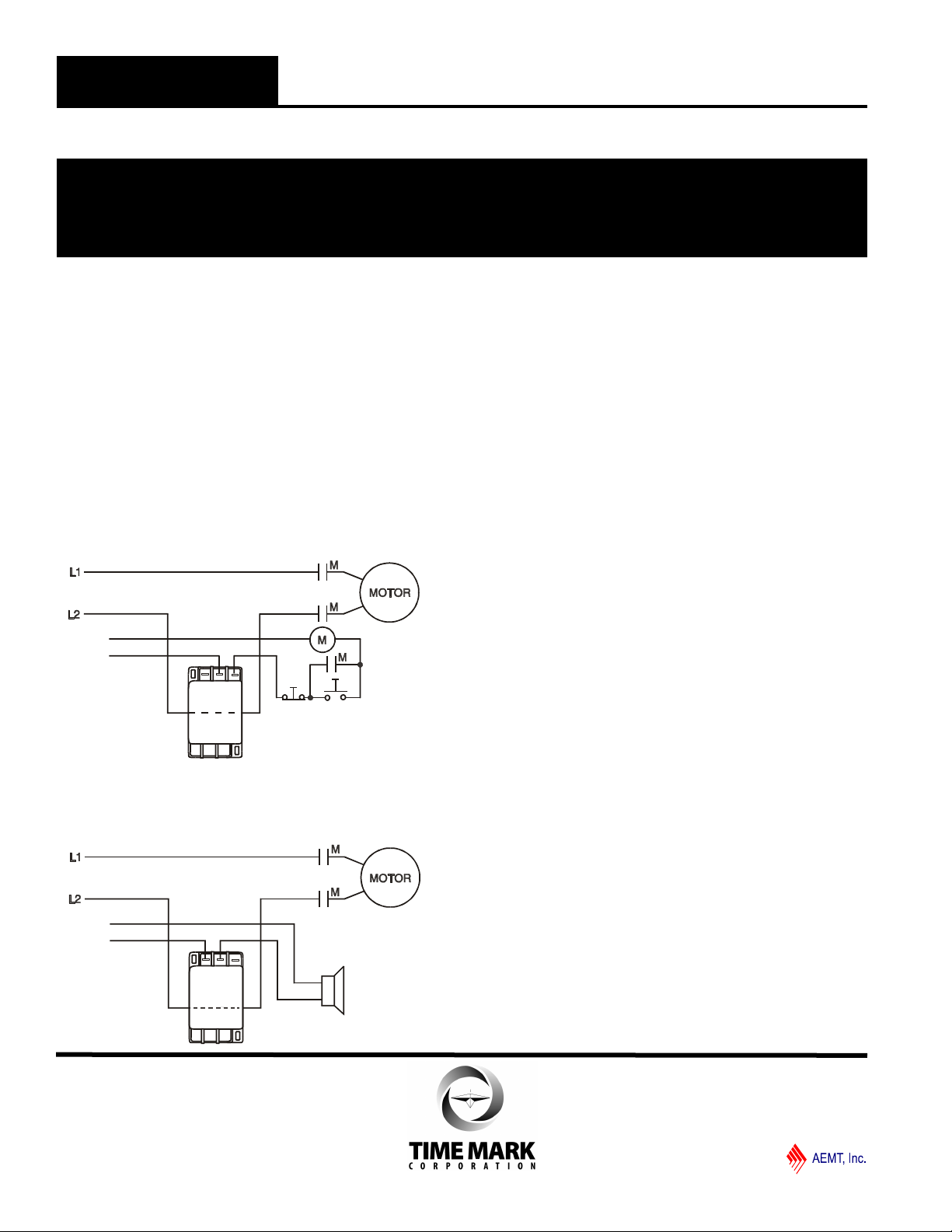
TYPICAL APPLICATION
- Under current
SPECIFICATIONS
Model 1732
Supply Voltage none required
Input Current Minimum: 25 amps
Adjustment Range 25 to 150 amps
Maximum Wire Size 2 AWG
Response Time 100ms
Contact Rating SPDT 10A at 240VAC resistive
Repeat Accuracy 1% max.
Dead Band Approximately 2%
Operating Temperature - 20° to +140° F
Reset Automatic
Terminals 1/4” quick connects
Enclosure Material ABS plastic
Mounting
Weight 3.5 oz.
Maximum: 150 amps
Surface Mount or DIN Rail 35mm
DIMENSIONS
11440 Ea s t Pin e S tre e t
Tu l sa , Okl ah om a 74 1 16
06/2015
© 2015 TIME MARK CORPORATION
Control
Voltage
ALARM
SHOWN WITHOUT
APPLIED POWER
NO C NC
Control
Voltage
SHOWN WITHOUT
APPLIED POWER
STOP
START
NO NCC
MODEL 1732
TIME MARK is a division of
AC Current Monitor
READ ALL INSTRUCTIONS BEFORE INSTALLING, OPERATING OR SERVICING THIS DEVICE.
KEEP THIS DATA SHEET FOR FUTURE REFERENCE.
GENERAL SAFETY
POTENTIALLY HAZARDOUS VOLTAGES ARE PRESENT AT THE TERMINALS OF THE MODEL 1732.
ALL ELECTRICAL POWER SHOULD BE REMOVED WHEN CONNECTING OR DISCONNECTING WIRING.
THIS DEVICE SHOULD BE INSTALLED AND SERVICED BY QUALIFIED PERSONNEL.
Installation Instructions
INSTALLATION
Mount the Model 1732 in a stable location, observing all
precautions as outlined in the GENERAL SAFETY section
above.
The Model 1732 has 1/4” quick connect terminals for
output connections. The monitored line must be passed
through the CT access hole, located in the side of the
Model 1732. Polarity is not important.
FOR OVER-CURRENT LOAD SHUT-OFF: connect the
load control circuit to the normally closed contact. This
contact will open on over-current, breaking the load circuit.
FOR OVER-CURRENT ALARM CIRCUIT: use the
normally open contact. This will close on over-current,
sounding the alarm.
FOR UNDER-CURRENT SENSING: reverse the contact
connections as stated above (use the normally open
contact for load shutoff, or the normally closed contact for
alarm).
ADJUSTMENT
The Model 1732 is screwdriver adjustable. To adjust the
current trip level, turn the SET POINT AMPS adjustment
clockwise or counter-clockwise until the desired trip setting
is reached.
TROUBLESHOOTING
Should the Model 1732 fail to operate properly, check that
power is present, and that current flow is within the normal
operating range. Check all fuses and verify that all wiring
connections are correct. Should problems persist, contact
the manufacturer.
WARRANTY
This product is warranted to be free from defects in
materials and workmanship for one year. Should this
device fail to operate, we will repair it for one year from the
date of manufacture. For complete warranty details, see
the Terms and Conditions of Sales page in the front
section of the Time Mark catalog or contact Time Mark at
1-800-862-2875.
11440 Ea s t Pin e S tre e t
Tu l sa , Okl ah om a 74 1 16
06/2015
© 2015 TIME MARK CORPORATION
 Loading...