

Page 1
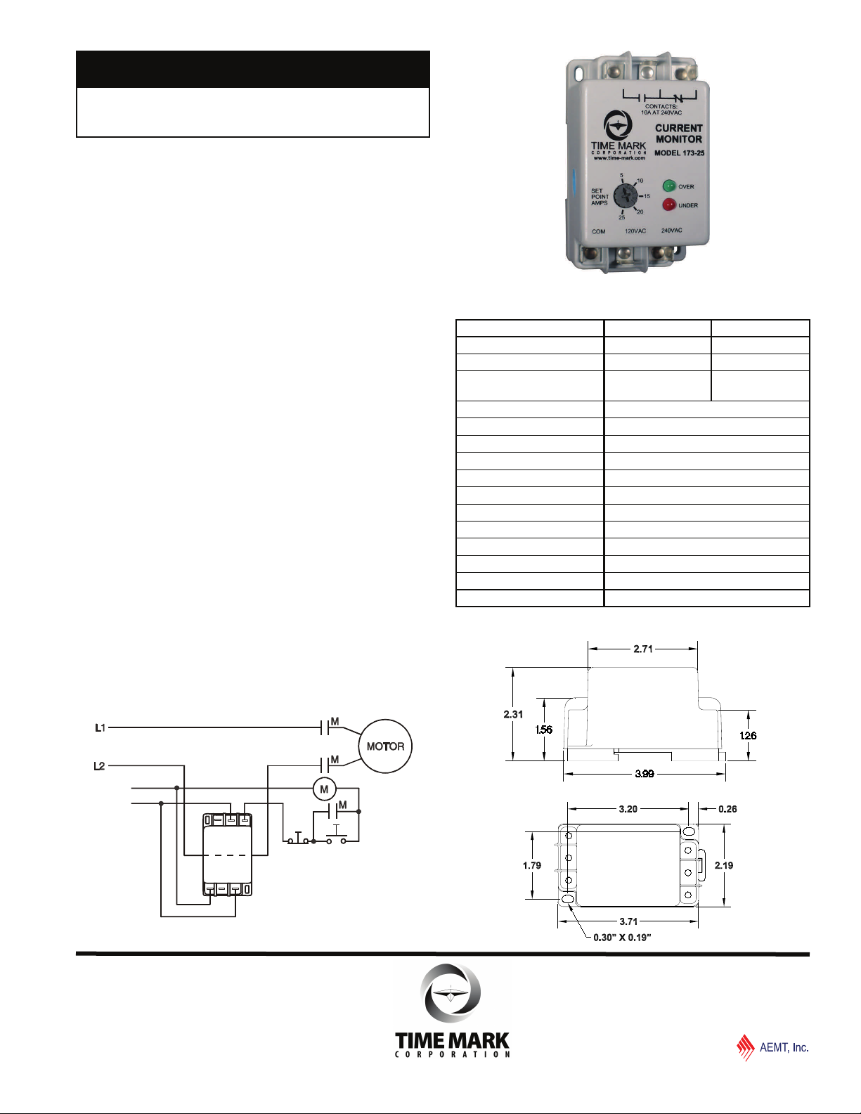
MODEL 173
AC Current Monitor
No CT Required
for Currents Up To 25 Amps
Quick Connect Terminals
Detects Over or Under Current
Surface or DIN Rail Mounting
DESCRIPTION
The Model 173 AC Current Monitor is a single setpoint AC current monitor. It can be used to detect either
over current or under current, depending on whether the
set point is set above or below the input current. The
OVER L E D illuminates and the relay energizes when
the current exceeds the set point. The UNDER L E D is
lit and the relay is de-energized when the current is less
than the set point.
Two versions, either of which can be connected to 120
or 240VAC, are available. One for current ranges up to
5 amps, the other for applications from 5 to 25 amps.
For currents above 25 amps, matching CT’s are
available.
can be used on AC currents from 50 to 400Hz.
The Model 173 is not frequency sensitive and
The compact housing can be surface or DIN rail
mounted with 1/4” quick connect terminals provided for
input and output connections.
SPECIFICATIONS
Model Number 173-5 173-25
Nominal Supply Voltage 120 or 240VAC 120 or 240VAC
Maximum Supply Voltage 150 or 260VAC 150 or 260VAC
Input Current 1 to 5 amps
600VAC
Power Consumption 240mA
VA Burden less than 0.5 watt
Response Time 100ms typical
Output Contact Rating SPDT 10A at 240VAC resistive
Repeat Accuracy 1% max
Dead Band 2%
Operating Temperature - 20º to +140º F
Reset Automatic
Terminals 1/4” quick connects
Enclosure Material ABS plastic
Mounting Options Surface Mount or DIN Rail 35mm
Weight 3 oz.
5 to 25 amps
600VAC
DIMENSIONS
TYPICAL APPLICATION
Control
Voltage
NO NCC
C
1
2
O
2
4
M
0
0
Over Current Sensing
STOP
SHOWN WITHOUT
APPLIED POWER
(other applications shown on page 2)
START
© 2015
TIME MARK is a division of
06/2015
TIME MARK CORPORATION
Page 2
A
A
MODEL 173
AC Current Monitor
READ ALL INSTRUCTIONS BEFORE INSTALLING, OPERATING OR SERVICING THIS DEVICE.
KEEP THIS DATA SHEET FOR FUTURE REFERENCE.
GENERAL SAFETY
POTENTIALLY HAZARDOUS VOLTAGES ARE PRESENT AT THE TERMINALS OF THE MODEL 173.
ALL ELECTRICAL POWER SHOULD BE REMOVED WHEN CONNECTING OR DISCONNECTING WIRING.
THIS DEVICE SHOULD BE INSTALLED AND SERVICED BY QUALIFIED PERSONNEL.
Installation Instructions
INSTALLATION
Mount the Model 173 in a safe location, observing all
precautions as outlined in the GENERAL SAFETY section
above.
The Model 173 has 1/4” quick connect terminals for power and
output connections. The monitored line must be passed
through the CT access hole located in the side of the Model
173. Polarity is not important. If an external CT is used, pass
one secondary lead through the Model 173, then connect the
secondary leads together.
For over-current load shutoff, connect the load control
circuit to the normally-closed contact. This contact will open
on over-current, breaking the load circuit. For an over-current
alarm circuit use the normally-open contact.
For under-current sensing, reverse the contact connections
as stated above; i.e., use the normally-open contact for load
shutoff or the normally-closed contact for alarm.
ADJUSTMENT
The Model 173 AC Current Monitor is screwdriver
adjustable. To adjust the trip level of the current, turn SET
POINT AMPS potentiometer clockwise or counter-clockwise
until the desired trip setting is reached.
TROUBLESHOOTING
Should this monitor fail to operate properly, check that power
is present and is of the correct voltage level. Check all fuses
and verify that all wiring connections are correct. Should
problems persist, contact your local Time Mark Distributor, or
the manufacturer at 800-862-2875.
WARRANTY
This product is warranted to be free from defects in materials
and workmanship for one year. Should this device fail to
operate, we will repair it for one year from the date of
manufacture. For complete warranty details, see the Terms
and Conditions of Sales page in the front section of the Time
Mark catalog or contact Time Mark at 1-800-862-2875.
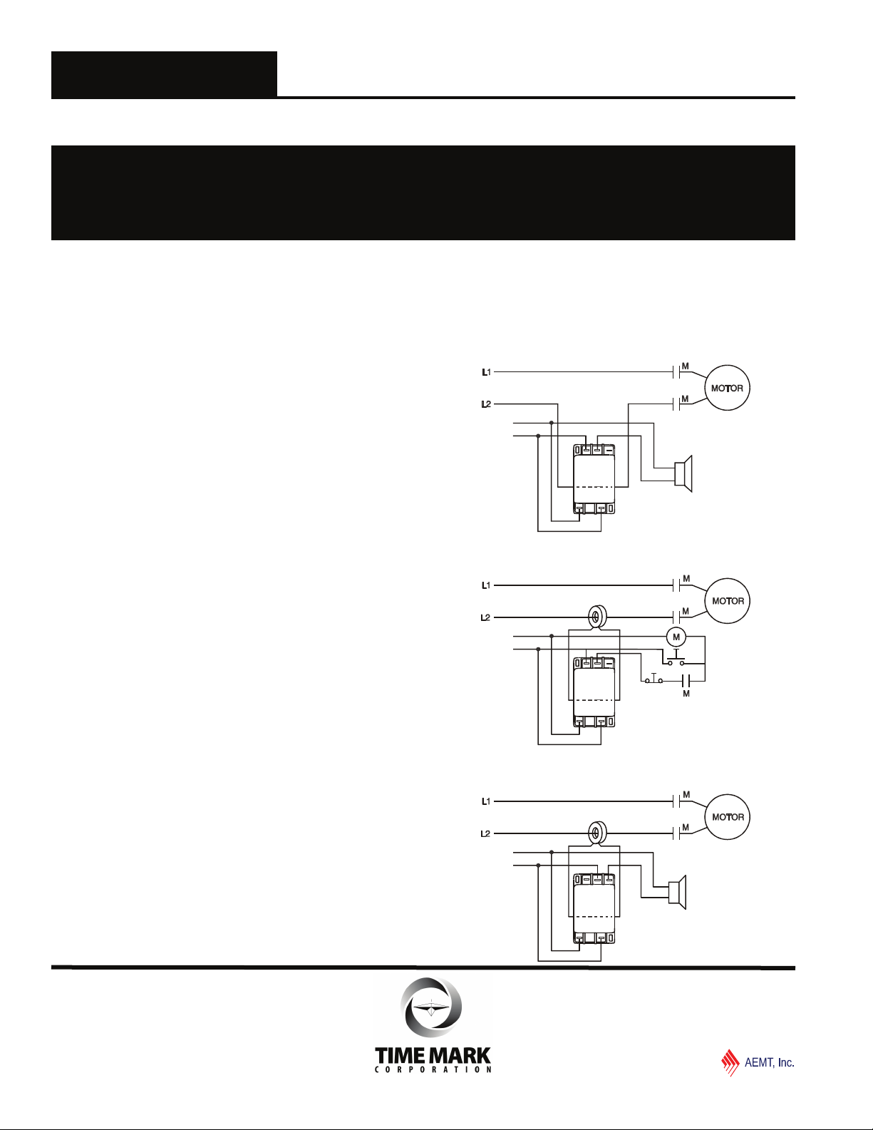
ADDITIONAL APPLICATIONS
- Over Current Alarm
Control
Volt age
NO C NC
C
1
O
2
M
0
2
4
0
SHOWN WITHOUT
PPLIED PO WER
ALARM
- Under Current with External CT
Control
Volt age
NO C NC
C
1
O
2
M
0
2
4
0
START
STOP
SHOWN WITHOUT
PPLIED PO WER
- Under Current Alarm with External CT
Control
Volt age
NO C NC
C
1
O
2
M
0
2
4
0
SHOWN WITHOUT
APPLIED POWER
ALARM
© 2015
06/2015
TIME MARK CORPORATION
TIME MARK is a division of
 Loading...