

Page 1
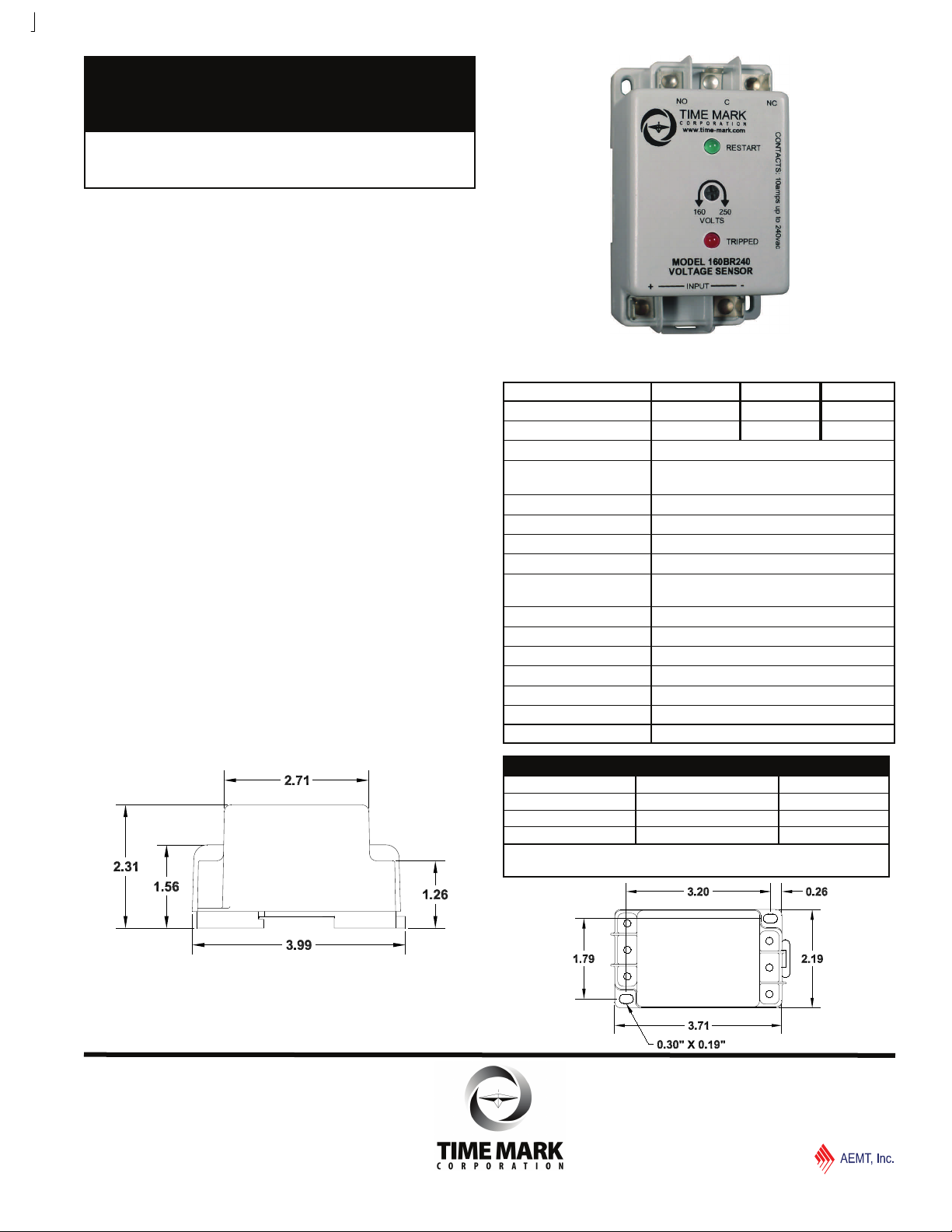
MODEL 160B
MODEL 160BR
Voltage Sensor
Detects Over or Under Voltage
Din Rail or Surface Mounting
Optional 5-minute Time Delay
DESCRIPTION
The Model 160B(R) Voltage Sensor is a single set-
point voltage sensor. Input voltages above the setpoint
cause the output contacts to energize. Input voltages
below the setpoint cause the output contacts to deenergize. The dead band between pull-in and drop-out
is less than 2%.
Wiring connections are made to 1/4” quick connect
terminals. Standard versions have a 2 second restart
delay. The ‘R’ versions of the Model 160B have a fixed
5 minute short cycle delay. The Model 160B has a
screwdriver adjustable setpoint range of approximately
35% of the maximum voltage.
The Model 160B is not frequency sensitive and may be
used in systems from 50 to 400Hz.
DIMENSIONS
SPECIFICATIONS
MODEL 160B120 160B240 160B480
Nominal AC Voltage 120VAC 208/240VAC 480VAC
AC Adjustment Range 80-130V 160-250V 380-480V
Frequency 50 - 400Hz
Short Cycle Delay Short cycle restart delay - 2 seconds
“R” versions - 5 minutes
Set-point Stability ± 1%
Dead Band ± 2%
Trip Delay 0.5 seconds - fixed
Contact Rating SPDT 10A at 240VAC resistive
Expected Relay Life Mech: 10 million operations
Elec: 100,000 operations at rated load
Termination Method 1/4” quick connect terminals
Operating Temperature - 20º to +131º F
Transient Protection 2500V for 10ms
Burden 5mA maximum
Enclosure Material ABS plastic
Mounting DIN Rail or Surface Mount
Weight 4 oz.
ORDERING INFORMATION
MODEL RESTART DELAY VOLTAGE
160B R 120VAC
240VAC
480VAC
Example: 160B - R - 240 orders a 240VAC sensor w/ optional 5 min delay.
Remove the “R” for the standard 2 second delay
Main (918) 438-1220
Sales (800) 862-2875
© 2015
TIME MARK is a division of
06/2015
TIME MARK CORPORATION
Page 2
MODEL 160B (R)
M
Voltage Sensor
READ ALL INSTRUCTIONS BEFORE INSTALLING, OPERATING OR SERVICING THIS DEVICE.
KEEP THIS DATA SHEET FOR FUTURE REFERENCE.
GENERAL SAFETY
POTENTIALLY HAZARDOUS VOLTAGES ARE PRESENT AT THE TERMINALS OF THE MODEL 160B.
ALL ELECTRICAL POWER SHOULD BE REMOVED WHEN CONNECTING OR DISCONNECTING WIRING.
THIS DEVICE SHOULD BE INSTALLED AND SERVICED BY QUALIFIED PERSONNEL.
Installation Instructions
INSTALLATION
The Model 160B can be mounted on a standard DIN Rail
or surface-mounted as required.
Attach 1/4” terminal lugs to the input voltage wires, and
connect to the terminals marked INPUT (refer to the
Typical Application diagram).
Apply power. The internal relay contacts transfer when the
input power is above the adjustable trip point.
For under voltage sensing, connect the load control
circuit to the terminal marked C and NO.
For over voltage sensing,connect the load control circuit
to the terminals marked C and NC.
ADJUSTMENT
Note: While adjusting the Model 160B you may wish to
jumper the control circuit contact to prevent the unit from
tripping the load off and on.
For under voltage sensing: Rotate the adjustment
clockwise until the failure indicator light just illuminates and
the contacts transfer. Slowly rotate the adjustment control
in a counter-clockwise direction until the failure indicator
goes out and the relay energizes. Any voltage below this
point will trip the relay off and illuminate the failure
indicator.
For over voltage sensing: Slowly rotate the adjustment
clockwise until the failure indicator just illuminates and the
relay de-energizes. Any voltage above this level will cause
the relay to energize and the failure indicator light to go
out.
Should nuisance tripping occur after either of the above
settings, turn the adjustment slightly farther as necessary.
TROUBLESHOOTING
Should the Model 160B(R) Voltage Sensor fail to operate,
check all connections. Verify that the proper source voltage
is present, and check all fuses. Should problems persist,
contact the factory for assistance.
WARRANTY
This product is warranted to be free from defects in
materials and workmanship for one year. Should this
device fail to operate, we will repair it for one year from
the date of manufacture. For complete warranty
details, see the Terms and Conditions of Sales page in
the front section of the Time Mark catalog or contact
Time Mark at 1-800-862-2875.
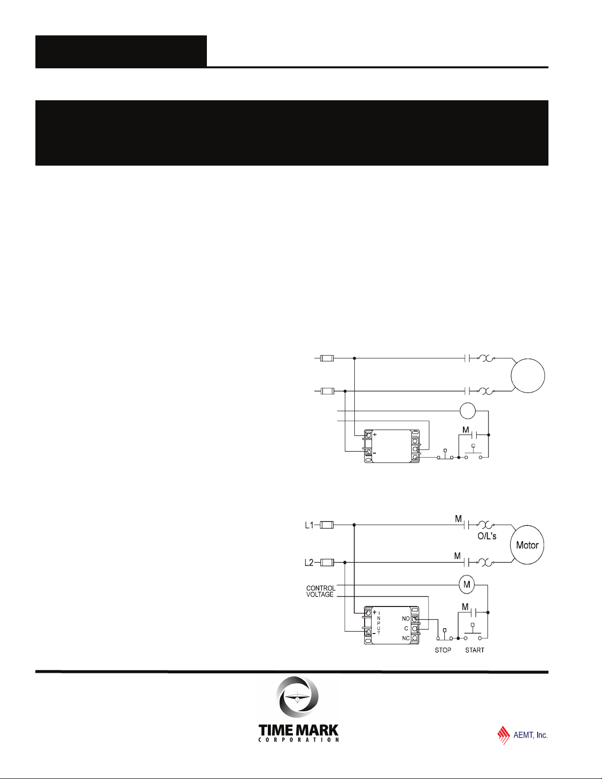
TYPICAL APPLICATION
OVER-VOLTAGE SENSING
L1
O/L’s
STOP
M
M
START
L2
CONTROL
VOLTAGE
T
NO
U
P
N
I
C
NC
Shows No Power Applied
TYPICAL APPLICATION
UNDER-VOLTAGE SENSING
Shows No Power Applied
MOTOR
Main (918) 438-1220
Sales (800) 862-2875
© 2015
06/2015
TIME MARK CORPORATION
TIME MARK is a division of
 Loading...