

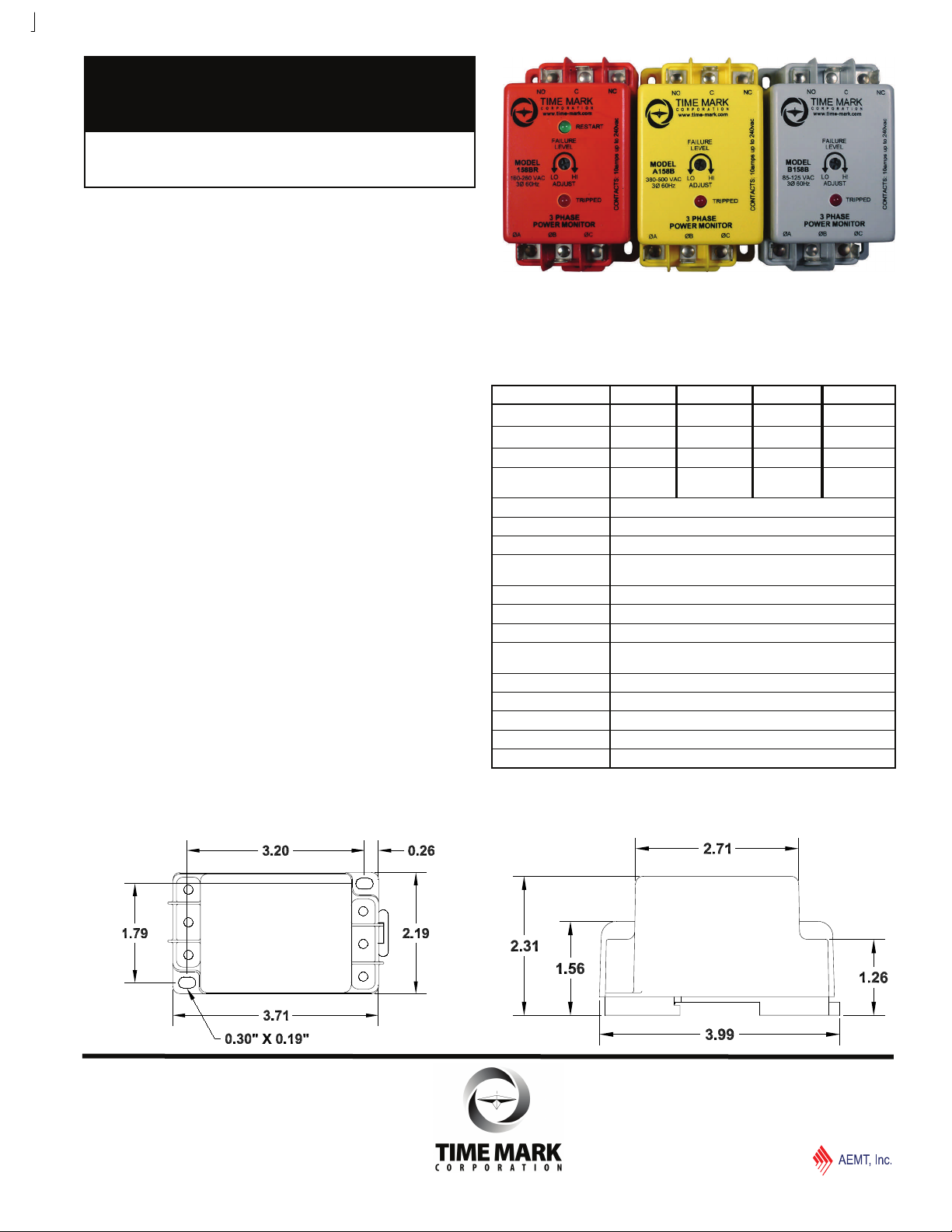
MODEL 158
MODEL 158R
3-Phase Monitor
DIN Rail Mount or Surface-mount
for HVAC Applications
Optional 5 Minute Short Cycle Time Delay
Detect Phase Loss, Low Voltage, Phase Reversal
5 Year Unconditional Warranty
DESCRIPTION
The Model 158 continuously monitors 3-phase power lines for
abnormal conditions. When properly adjusted, the Model 158
monitor will detect phase loss on a loaded motor even when
regenerated voltage is present.
This device consists of a solid-state voltage and phase-angle
sensing circuit, driving an electro-mechanical relay. When
correct voltage and phase rotation are applied, the internal
relay will energize. A fault condition will de-energize the relay.
When the fault is corrected, the monitor will automatically
reset.
The Model 158 does not require a neutral connection, and
can be used with Wye or Delta systems. Four versions cover
120V, 208/240V, 480V (60Hz) and 380V (50Hz). Voltage
ranges are sufficient to allow for proper adjustment to existing
conditions. A front-mounted L E D failure indicator is provided.
The “R” versions of the Model 158 Monitor have an additional
L E D indicator for RESTART, and a 5 minute short cycle
timer, to delay restarting the motor.
The Model 158 can be DIN Rail or Surface Mounted.
SPECIFICATIONS
MODEL B158B 158B A158B EX158B
Input Voltage 120VAC 208/240VAC 480VAC 380VAC
Adjustment Range 85-125VAC 160-260VAC 380-500VAC 300-400VAC
Frequency 60Hz 60Hz 60Hz 50Hz
Power Consumption
(per phase)
Transient Protection 2500 VRMS of 10ms
Repeat Accuracy ± 0.1% of setpoint (fixed conditions)
Response Time 0.5 seconds
Reset Time Short cycle restart delay - 2 seconds
Reset Type Automatic
Dead Band 2%
Output contacts SPDT 10A at 240VAC resistive
Expected Relay Life Mech: 10 million operations
Operating Temp -20° to +131° F
Humidity Tolerance 97% w/o condensation
Enclosure Material ABS plastic
Mounting DIN Rail or Surface Mount
Weight 5 oz.
ADDITIONAL ORDERING INFO:
add an “R” to any 158 model number above, for the 5 minute time delay option
.25W .5W 1.5W 1.25W
“R” versions - 5 minutes
Elec: 100,000 operations at rated load
DIMENSIONS
© 2015
TIME MARK is a division of
06/2015
TIME MARK CORPORATION
MODEL 158 (R)
3-Phase Monitor
READ ALL INSTRUCTIONS BEFORE INSTALLING, OPERATING OR SERVICING THIS DEVICE.
KEEP THIS DATA SHEET FOR FUTURE REFERENCE.
GENERAL SAFETY
POTENTIALLY HAZARDOUS VOLTAGES ARE PRESENT AT THE TERMINALS OF THE MODEL 158.
ALL ELECTRICAL POWER SHOULD BE REMOVED WHEN CONNECTING OR DISCONNECTING WIRING.
THIS DEVICE SHOULD BE INSTALLED AND SERVICED BY QUALIFIED PERSONNEL.
Installation Instructions
INSTALLATION
Mount the Model 158 3-Phase Monitor in a suitable
enclosure.
Attach 1/4” terminal lugs to the input voltage wires, and then
connect them to the terminals on the Model 158 marked ØA,
ØB, and ØC. Proper clockwise phase rotation should be
confirmed, using a Time Mark Model 108A or 108B Phase
Rotation Indicator or unit will show trip for Phase Reversal.
Attach 1/4” terminal lugs to the load control circuit wires, then
connect them to the terminals marked C and NO.
Apply power. The NO contact will close when correct voltage
is applied. If a Model 158R is being installed, there will be
a 5 minute delay before the contact transfers. The green
RESTART light should be ON during this 5 minute period.
ADJUSTMENT PROCEDURE
NOTE: While adjusting the trip level, you may wish to jumper
the control circuit contacts to prevent the device from tripping
the load on and off.
Slowly rotate the FAILURE LEVEL ADJUST pot clockwise,
until the TRIPPED indicator L E D just illuminates, and the
contacts transfer.
Rotate the FAILURE LEVEL ADJUST pot counter-clockwise,
until the TRIPPED indicator L E D goes out, and the contacts
re-energize. On the “158R” version, the green RESTART
light will be ON, and there will be a 5 minute delay period
before the contacts re-energize.
Should nuisance tripping occur, after completing these adjustments, turn the FAILURE LEVEL ADJUST pot slightly further
counter-clockwise, as necessary.
the control circuit contact, if one was applied.
TROUBLESHOOTING
There are no user-serviceable parts in the Model 158 3Phase Monitor. Should the unit fail to operate properly, check
that correct voltage and clockwise phase rotation are being
applied. Check all fuses and wiring connections. Should
problems persist, contact your local Time Mark Distributor, or
the factory at 800-862-2875 (Monday-Friday; 8 a.m. to 5 p.m.
CST), for further assistance.
Remove the jumper from
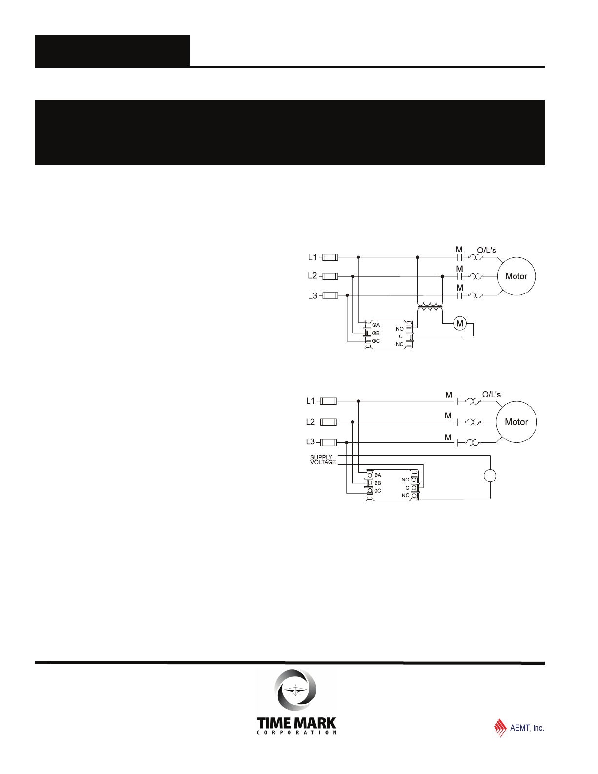
APPLICATION DIAGRAMS
Typical compressor application
Shows No Power Applied
Typical motor control application
optional
Shows No Power Applied
WARRANTY
This product is warranted to be free from defects in materials
and workmanship, and is covered by our exclusive 5-year
Unconditional Warranty. Should this device fail to operate
for any reason, we will repair it for five years from the date of
manufacture. For complete warranty details, see the Terms
and Conditions of Sales page in the front section of the Time
Mark catalog or contact Time Mark at 1-800-862-2875.
alarm
.
© 2015
TIME MARK is a division of
06/2015
TIME MARK CORPORATION
 Loading...