

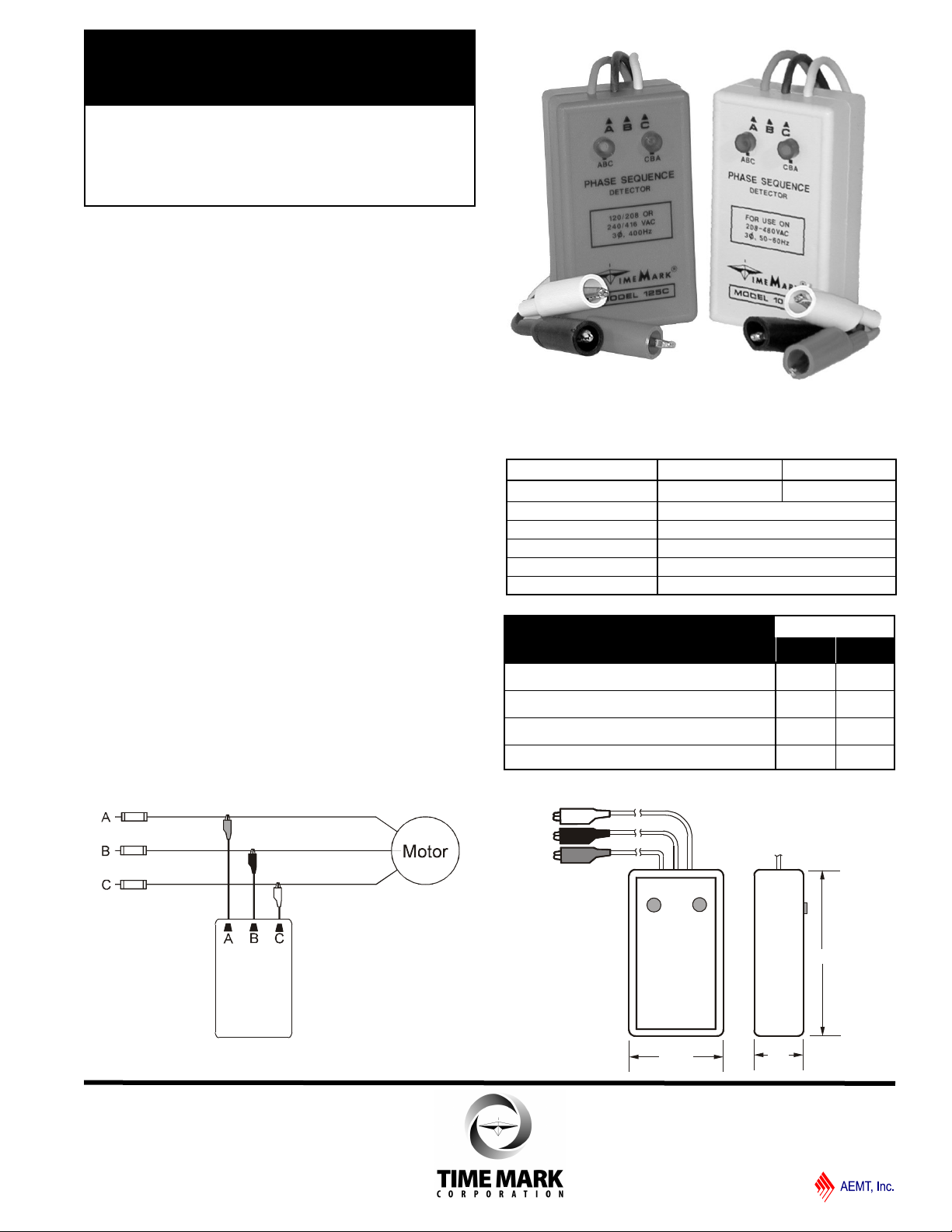
1.2"
4.0"
2.25"
18" leads
A B
C
Model 108
MODEL 108B
TIME MARK is a division of
MODEL 125C
Phase Sequence
Detector
Indicates Phase Sequence
Detects Loss of One or More Phases
Compact & Lightweight
Color-coded Leads
DESCRIPTION
The Models 108B (50/60Hz) and Model 125C (400Hz)
Phase Sequence Detectors permit the operator to
quickly and easily determine proper phase sequence
(either ABC or CBA). This can be vitally important
information when installing, or making wiring changes to
motor s, wa ttm eters , tra nsform ers, electrical
installations, power factor meters or generators.
To use, connect the Detector to any 3-phase circuit from
208 to 480 volts, Wye or Delta. Proper phase
sequence, and all phases present will illuminate the
ABC lamp. An open phase condition will illuminate both
lamps. If two or more phases are open, neither lamp will
illuminate. See the Condition Chart.
TYPICAL APPLICATION
SPECIFICATIONS
MODEL 108B 125C
Frequency 50/60Hz 400Hz
Voltage (phase to phase) 208 - 480VAC
Leads 18” color-coded
Lead Termination Alligator clips
Weight 8 oz. max.
Enclosure Material ABS plastic
CONDITION
CHART
ABC Rotation
CBA Rotation
ONE Phase Open
2 OR MORE Phases Open
LAMP(S) LIT
ABC CBA
DIMENSIONS
11/2011
© 2011 TIME MARK CORPORATION
Voltage
Voltage
A
BC
A
B C
MODEL 108B
TIME MARK is a division of
MODEL 125C
Phase Sequence Detectors
READ ALL INSTRUCTIONS BEFORE INSTALLING, OPERATING OR SERVICING THIS DEVICE.
KEEP THIS DATA SHEET FOR FUTURE REFERENCE.
GENERAL SAFETY
POTENTIALLY HAZARDOUS VOLTAGES ARE PRESENT AT THE TERMINALS OF THE MODEL 108B OR 125C
DETECTORS. ALL ELECTRICAL POWER SHOULD BE REMOVED WHEN CONNECTING OR DISCONNECTING
WIRING. THIS DEVICE AND WIRING SHOULD BE INSTALLED AND SERVICED BY QUALIFIED PERSONNEL.
OPERATOR INSTRUCTIONS
CONNECTION
Connect the three clip leads to the 3-phase power source.
Apply AC power. One of the detector lamps should
illuminate, indicating the phase sequence as connected. If
the desired phase sequence is not lit, change any two of
the three leads.
Read the 3-phase designation on the front panel; connect
the corresponding leads to your equipment.
If both lamps illuminate, check for a loss of voltage on one
of the three phases. If neither lamp illuminates, check for a
loss of voltage.
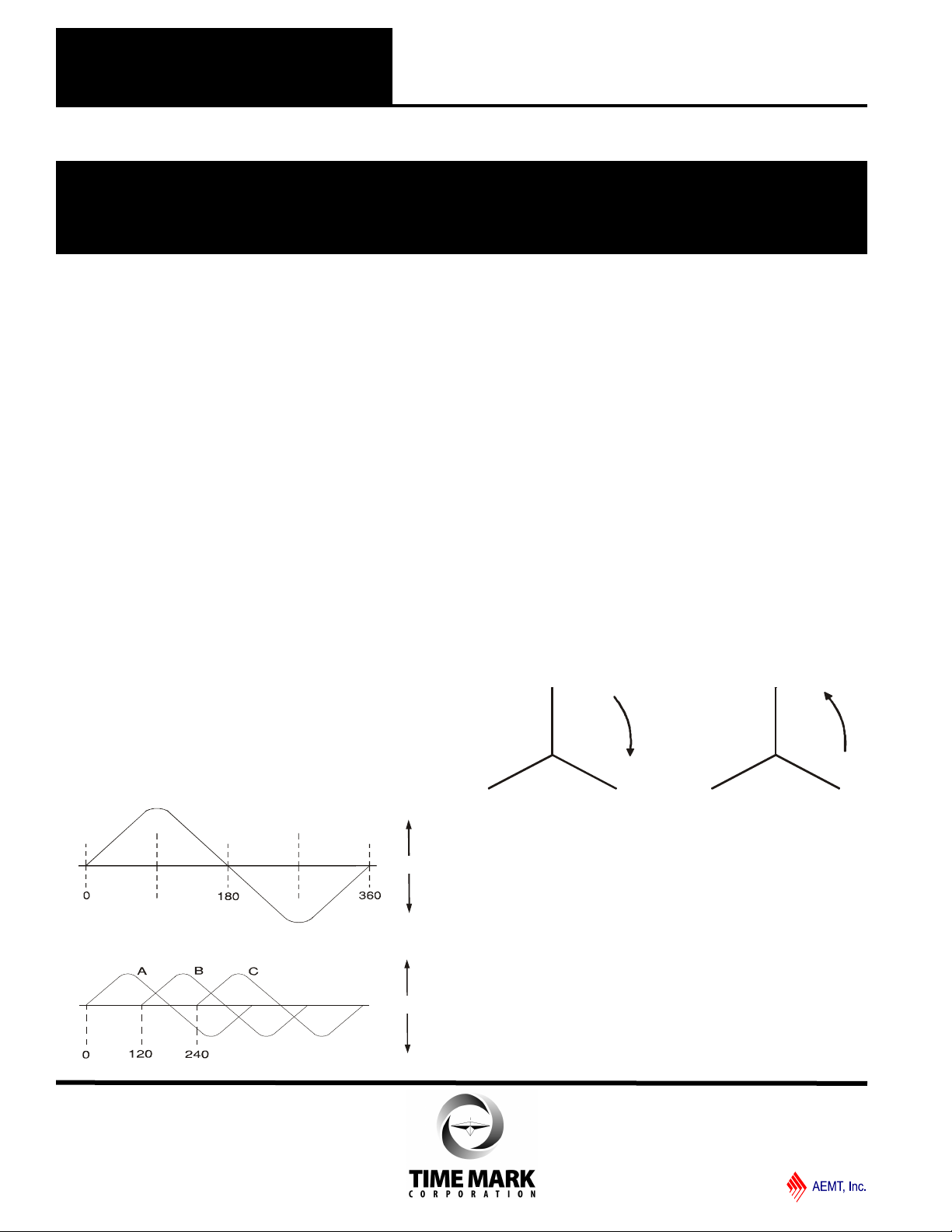
3-PHASE POWER BASICS
In 3-phase power there are three lines which carry the
voltage, normally designated as A-B-C. In some
installations however, they may be designated L1-L2-L3 or
T1-T2-T3. The phase sequence as generated is A-B-C.
As the voltage on these lines rotates through 360 degrees,
phase B lags phase A by 120 degrees; while phase C lags
phase A by 240 degrees. The voltage on each of these
lines vary as shown in figure 1, a graph of voltage versus
degrees of rotation.
figure 1.
figure 2.
If all phases are shown on the same graph, they would
appear as shown in figure 2.
Pictured on a rotating phasor diagram, the angle
between each phase is fixed at 120 degrees as they
rotate in unison at the line frequency (see figure 3).
In figure 4 you can see that if any two phases are
reversed, the direction of rotation will be in the opposite
direction. This reversal of the rotating sequence will
cause motors to run in the opposite direction. Many
other types of equipment are phase sensitive and will
not perform as intended if the phase sequence is
incorrect.
figure 3. figure 4.
WARRANTY
This product is warranted to be free from defects in
materials and workmanship, and is covered by our
exclusive 5-year Unconditional Warranty. Should
this device fail to operate for any reason, we will repair
it for five years from the date of manufacture. For
complete warranty details, see the Terms and
Conditions of Sales page in the front section of the
Time Mark catalog or contact Time Mark at 1-800-862-
2875.
11/2011
© 2011 TIME MARK CORPORATION
 Loading...