

Page 1

All rights reserved © TimeLink microsystems
TMS2000
USER’S MANUAL
Reference :
MN0474
Release :
A0
Date :
2015-01-07
Page 2

TMS2000
USER’S MANUAL
Reference :
MN0474
Date :
2015-01-07
issue :
A0
Page:
2/21
All rights reserved © TimeLink microsystems
CHANGES IN THE DOCUMENT
Release
DATE
OBJECT of CHANGE
A0
2016-06-15
From original French release A3(2015-01-07)
Name- Responsibility-Service-Company
Date & Signature
Written by
Christophe GRAULLE
Ingénieur de développement - TimeLink microsystems
2014-10-09 / CG
Approval
Jean-Claude POUYTES
Responsible Quality - Time Link microsystems
2014-10-09 / JCP
Page 3

TMS2000
USER’S MANUAL
Reference :
MN0474
Date :
2015-01-07
issue :
A0
Page:
3/21
All rights reserved © TimeLink microsystems
CONTENTS
Sommaire
1. GENERAL DESCRIPTION 5
1.1. FRONT and REAR FACE ................................................................................................................................ 5
1.2. FUNCTIONNAL CARACTERISTICS.................................................................................................................. 6
1.3. MECHANICAL CHARACTERISTICS ................................................................................................................. 6
2. BEFORE ANY USE 7
2.1. INSTALLING THE UNIT .................................................................................................................................. 7
2.2. CONNECTIONS ............................................................................................................................................. 7
2.3. PARAMETERS ............................................................................................................................................... 7
2.3.1. Parameters of the TMS2000 unit .......................................................................................................... 8
3. USE 10
3.1. Power On ................................................................................................................................................... 10
3.2. Lights 10
3.2.1. Voyants pendant le démarrage de l'équipement ................................................................................ 10
3.3. Interfaces of the equipment ...................................................................................................................... 11
3.3.1. NTP Service .......................................................................................................................................... 11
3.3.2. SSH access ............................................................................................................................................ 12
3.3.3. Access from the console ...................................................................................................................... 13
4. SURVEILLANCE 13
4.1. http server ................................................................................................................................................. 13
4.1.1. Setting time manually .......................................................................................................................... 16
4.2. UDP frame ................................................................................................................................................. 17
5. MAINTENANCE 19
5.1. Updating the software ............................................................................................................................... 19
5.2. File for the update ..................................................................................................................................... 19
5.3. Resetting the GNSS .................................................................................................................................... 19
Page 4

TMS2000
USER’S MANUAL
Reference :
MN0474
Date :
2015-01-07
issue :
A0
Page:
4/21
All rights reserved © TimeLink microsystems
6. ANNEXES 20
6.1. Changing the configuration files ................................................................................................................ 20
6.1.1. Changing from equipment ................................................................................................................... 20
6.1.2. Changing from a PC equipped with an SD card reader ........................................................................ 20
TABLE OF ILLUSTRATIONS
Figure 1 – Front face of the TMS2000 ........................................................................................................................... 5
Figure 2 – Rear face of the TMS2000 ............................................................................................................................ 5
Tableau 1 – Functional specifications TMS2000 ........................................................................................................... 6
Tableau 2 – Mechanical specifications .......................................................................................................................... 6
Tableau 3 – LEDs status during start up ...................................................................................................................... 10
Page 5
TMS2000
USER’S MANUAL
Reference :
MN0474
Date :
2015-01-07
issue :
A0
Page:
5/21
All rights reserved © TimeLink microsystems
1. GENERAL DESCRIPTION
This document is dedicated to TMS2000 equipment, a time server using Network Time Protocol to deliver precise
time.
1.1. FRONT and REAR FACE
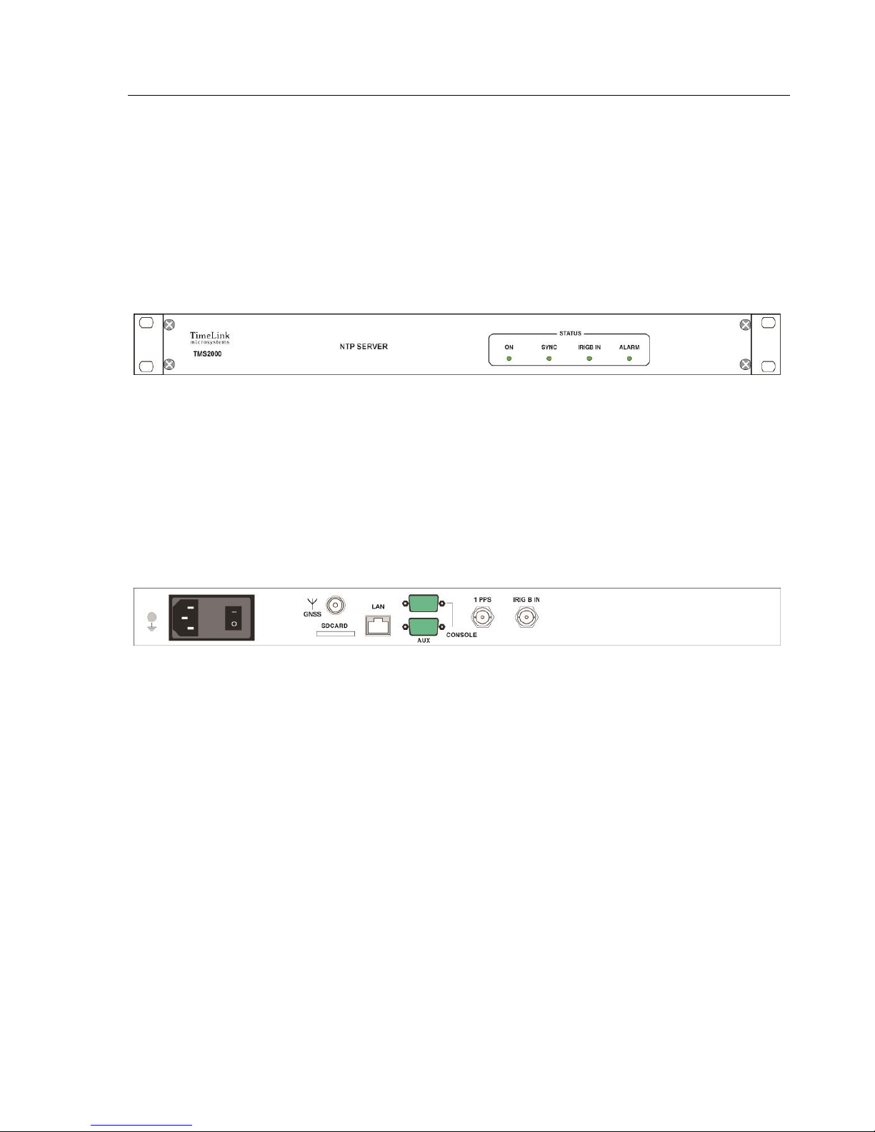
The front face of the equipment shows 4 LED’s indicating the current status of the unit.
Figure 1 – Front face of the TMS2000
On the front face are located all the connectors.
Figure 2 – Rear face of the TMS2000
Page 6

TMS2000
USER’S MANUAL
Reference :
MN0474
Date :
2015-01-07
issue :
A0
Page:
6/21
All rights reserved © TimeLink microsystems
1.2. FUNCTIONNAL CARACTERISTICS
Table below shows the main specifications of the unit:
.
Characteristic
Types / Values
1PPS output
level : 0-5V, positive pulse, 50 Ohms
BNC female socket - Identification "1PPS"
Duration : 1ms, period 1Hz, reference rising front
IRIGB input
Modulated analog signal 1:1/1:3 level 0,6-6Vcc, charge 600Ω
BNC female socket - Identification "IRIG B IN"
SD card
"push-push" connector type accessible from the rear face of the unit .
Identification "SD-Card"
Power supply input(s)
CEE 2P+T socket with filter and switch On/Off
Input 90-264VAC / 47-63Hz
Consumption : <10W on 230VAC/50 Hz
Network
Ethernet 100 Mbps
RJ45 socket - Identification "LAN"
NTP
Port UDP 123, operating mode Request/Reply (unicast)
Console
DB-9 connector, speed 115200 bauds, 8bits, 1 bit stop
Service SSH
Port TCP 22
Service HTTP
Port TCP 80
Remote control
UDP frame sent to a list of IP address, PORT number
Tableau 1 – Functional specifications TMS2000
1.3. MECHANICAL CHARACTERISTICS
Table below shows the mechanical characteristics of the unit:
characteristics
Types / Values
Dimensions
Rack 19" (483 mm) height 1U (44 mm), depth 350 mm.
Masse
2.7 Kg (3.0 Kg with power supply cable).
Tableau 2 – Mechanical specifications
Page 7

TMS2000
USER’S MANUAL
Reference :
MN0474
Date :
2015-01-07
issue :
A0
Page:
7/21
All rights reserved © TimeLink microsystems
2. BEFORE ANY USE
Before using the equipment, it’s necessary to perform the operations described below.
2.1. INSTALLING THE UNIT
The equipment is intended to be integrated in a 19 "cabinet.
It is recommended to connect the equipment to the protective mechanical ground of the bay and grounded via the
ground bolt to the left rear of the equipment.
2.2. CONNECTIONS
The equipment must be connected to the mains using the supplied cable.
The equipment must be connected to Ethernet with an RJ45 cable (not supplied).
Important: Power must be set after all connections.
2.3. PARAMETERS
The proper functioning of equipment required to set them with consistent values for the critical parameters. These
parameters are located on an inserted SD card on the back of each equipment. The parameters available to the
user are in the file "user.ini".
When “setting” the SD card into a PC the file 'user.ini' is located in the "TMS2000" SD-Card. However, if you want
to edit this file from the device it is in '/ config'.
The following tables list the parameters according to their location in the configuration space.
The procedure to change the settings is described in an appendix to this document.
Important: Please do not modify files other than those mentioned below under pain of not having functional
equipment except if support staff from Timelink Microsystems invites you to do so.
Page 8

TMS2000
USER’S MANUAL
Reference :
MN0474
Date :
2015-01-07
issue :
A0
Page:
8/21
All rights reserved © TimeLink microsystems
2.3.1. Parameters of the TMS2000 unit
These parameters are located in the file 'TMS2000/user.ini' of the card.
Section [NETWORK]
Name
Description
Presence
Default value
Authorized values
IP
Show the IP v4 address of
the unit
mandatory
192.168.10.190
Any valid IP address
MASK
The sub network mask on
which the equipment is
located
mandatory
255.255.255.0
Tout masque de sousréseau valide
MAC
Show the MAC address of
the equipment
mandatory
Predefined in
factory according
to serial number
of the unit
Any valid MAC address
Nota: except in special
cases, should not be
changed.
GW
The IP v4 router address of
the sub network on which
the equipment is located
Optional but
recommended to
reach other
subnets
192.168.10.254
Any valid IP address
BROADCAST
indicates the IPv4
broadcast address for the
equipment on its subnet
optional
192.168.10.255
Any valid broadcast
address
NAMESERVER
Indicates the IP v4 address
of the server of names
used to resolve the
machine’s names.
Optional but
essential if the
machine names
are used in other
settings (eg, names
of NTP servers to
reach)
8.8.8.8
Any valid IP address
Section [NTP_SERVER]
Name
Description
Presence
Default value
Authorized values
ENABLE
Enable or disable the NTP
server of the equipment
mandatory
Y
Do not change this value
under penalty of no
longer having NTP
service in the
equipment
VERSION
Sets the version contained
in the response to NTP
requests
mandatory
AUTO
V3: for a response with
a release 3 packet.V4:
for a response with a
release 4 packet. AUTO:
to adapt the response to
the request
Page 9

TMS2000
USER’S MANUAL
Reference :
MN0474
Date :
2015-01-07
issue :
A0
Page:
9/21
All rights reserved © TimeLink microsystems
Name
Description
Presence
Default value
Authorized values
NOTIME
Define the behavior in case
of impossibility to deliver a
right time
mandatory
NO_ANSWER
NO_ANSWER: no
response to the NTP
request if the time
could not be provided
LEAP: the NTP packet
will contain the flag
'LEAP' indicating that
the server doesn’t
provide a right time.
Section [IRIGB_IN]
Name
Description
Presence
Default value
Authorized values
ENABLE
Enable or disable the
acquisition of the IRIG-B
signal
mandatory
Y
Don’t change this value
otherwise the
acquisition of the IRIG-B
signal will stop.
equipment
CODE
Define the contents of the
IRIG-B signal
mandatory
2
Don’t change this value
YEAR
Define the year of the IRIGB signal
mandatory
2014
Don’t change this value
Section [GPS]
Nom
Description
Presence
Default values
Authorized value
UTC_OFFSET
Offset between the GPS
hour and the UTC hour
mandatory
16
Section [RM]
Nom
Description
Presence
Default values
Authorized value
PUSH_TO
Give the list of the
‘IP:Port' to which send
information to remote
management. Couples IP:
Port 'are separated by ', '.
mandatory
192.168.10.191:9000
All 'IP:Port' couple
valid on the network
where the server is
connected.
Page 10

TMS2000
USER’S MANUAL
Reference :
MN0474
Date :
2015-01-07
issue :
A0
Page:
10/21
All rights reserved © TimeLink microsystems
Note: There are other parameters in the file 'user.ini' but these should not be changed without the agreement of
TimeLink microsystems. These settings are located under the following banner:
#----------------------------------------------------------------------------#
# >>>> DO NOT MODIFY PARAMETERS UNDER THIS LINE <<<<
#----------------------------------------------------------------------------#
3. USE
3.1. Power On
Equipment starts from power by switching the button On / Off on the '1' position.
Notes:
1. During the startup of the operating system, the front face indicator LEDs remain off for about fifteen seconds
after power On.
2. Equipment having very low consumption, it is necessary to wait 30 seconds between a power off and a new
power on to allow a full stop. An OFF / ON cycle too short can lead to a bad start equipment.
3.2. Lights
On the front face the group of LEDs gives the status of the equipment. These LEDs and their meaning are described
in the following sections.
3.2.1. Voyants pendant le démarrage de l'équipement
Pendant le démarrage de l'équipement les LEDs de la face avant indiquent une progression ou un code d'erreur.
Le tableau suivant récapitule les combinaisons de LEDs durant cette étape.
ON
SYNC
IRIGB
ALARM
Description
Yellow
Off
Off
Off
Mounting the SD-Card
Red
Red
Red
Red
SD car missing or not detected
Green
Green
Yellow
Off
Start up the configuration
Red
Off
Off
Red
IP address is missing
Off
Red
Off
Red
Network mask is missing
Off
Off
Red
Red
MAC address is missing
Green
Green
Green
Yellow
Start up of the application proper to the equipment
Green
Green
Green
Green
Application has start up
Blue
Blue
Blue
Red
Application stopped in error
Yellow
Yellow
Yellow
Red
Application doesn’t start up
Tableau 3 – LEDs status during start up
Page 11

TMS2000
USER’S MANUAL
Reference :
MN0474
Date :
2015-01-07
issue :
A0
Page:
11/21
All rights reserved © TimeLink microsystems
LEDs during operation of the TMS 2000 equipment
LEDs
Color
meaning
ON
White
The system booted
SYNC
Red
The system is not synchronized to the GNSS signal
Yellow
GNSS source is not the selected source
Green
The system is synchronized to the GNSS signal
Off
GPS source has been disabled
IRIGB
Red
The system is not synchronized to the IRIG-B signal
Yellow
IRIG-B source is not the selected source
Green
The system is synchronized to the IRIG-B signal
Off
IRIG-B source has been disabled
ALARM
Green
No alarm is present or at least one alarm “information” type is present
Yellow
At least one alarm "warning" type was generated
Red
At least one alarm "error" type was generated
3.3. Interfaces of the equipment
The equipment provides the following interfaces :
One connector providing 1 PPS signal
One connector for IRIG-B input signal
One connector for Ethernet 100Mbits
a slot for an SD card
a 4 LEDs display
On the Ethernet interface the following functionalities are available:
• NTP service in IP v4
• SSH access by IP v4
• HTTP access
• Access to a UDP frame v4
3.3.1. NTP Service
This service offers the ability to synchronize this equipment with an NTP client. The times generated are those of
the internal time itself synchronized to one of the source connected to the equipment.
The service is able to respond in NTPV3 or NTPV4 depending on its configuration. In case of unavailability of the
internal time it can, depending on its configuration, respond with the flag LEAP positioned or else doesn’t respond.
Page 12

TMS2000
USER’S MANUAL
Reference :
MN0474
Date :
2015-01-07
issue :
A0
Page:
12/21
All rights reserved © TimeLink microsystems
3.3.2. SSH access
This service provides access to the device from another computer in safe mode.
Only the user « maintenance” has authorization to connect to the equipment. After connecting a shell is opened
on the machine. So it should be paid to actions from this moment on pain of no longer serve the primary functions
of the equipment.
Possible actions from the shell are:
• to update the system software
• change a user's password
• restart or shut down equipment
• log in as 'root'
The default password is « tms2000 ».
3.3.2.1. Updations the system
The system update is done using the tool 'update' provided.
Refer to the section Maintenance to see how.
3.3.2.2. Changing password
To change the password of a user you must use the command 'passwd [<user>]'. You will be requested the new
password and it will be written in the SD card file.
Note: When the user “maintenance” changes his password, it must respect the following rules:
• length of 8 characters at least
• at least three of four criteria: a tiny (a-z), a capital letter (A-Z), a number (0-9), a special character ($, @, ...)
• The password must be sufficiently different from the current password
• The password cannot be the host name (including permutation of characters, different case).
Failure to comply with these rules results in the rejection of the password.
For the root user, the non compliance is indicated but the password is nonetheless forced.
3.3.2.3. Restart or shutdown the equipment
These functions allow to restart or to stop safely the equipment. You first need to be root to enable these features
(see below).
To restart type 'reboot' and stop type 'poweroff'. After a 'poweroff' you can turn off the equipment.
3.3.2.4. Become 'root'
This function allows the user to change his identity in that of root.
For this type '/ tools / su' and enter the password for the root user (default: tms2000 ").
Page 13
TMS2000
USER’S MANUAL
Reference :
MN0474
Date :
2015-01-07
issue :
A0
Page:
13/21
All rights reserved © TimeLink microsystems
3.3.3. Access from the console
The system can be accessed from the console port by connecting a terminal emulator. Use the following settings:
• speed 115200
• 8 bits, 1 stop bit, no parity
You can access the command shell as when using the access via SSH after you 'logged' on the system.
Once the command shell you can perform the same actions as described above.
4. SURVEILLANCE
Equipment monitoring can be done via the integrated web server or by receiving a UDP frame containing
information on the equipment.
4.1. http server
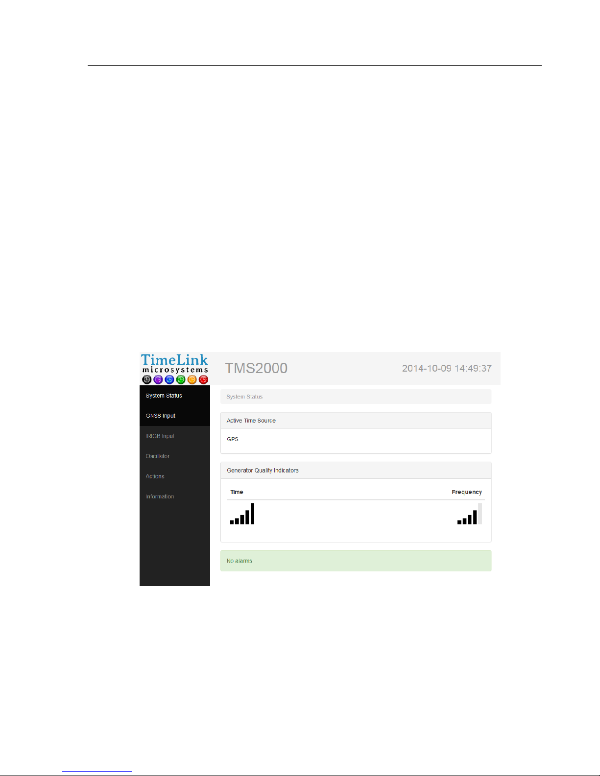
The HTTP server is accessible on port 80 to the equipment.
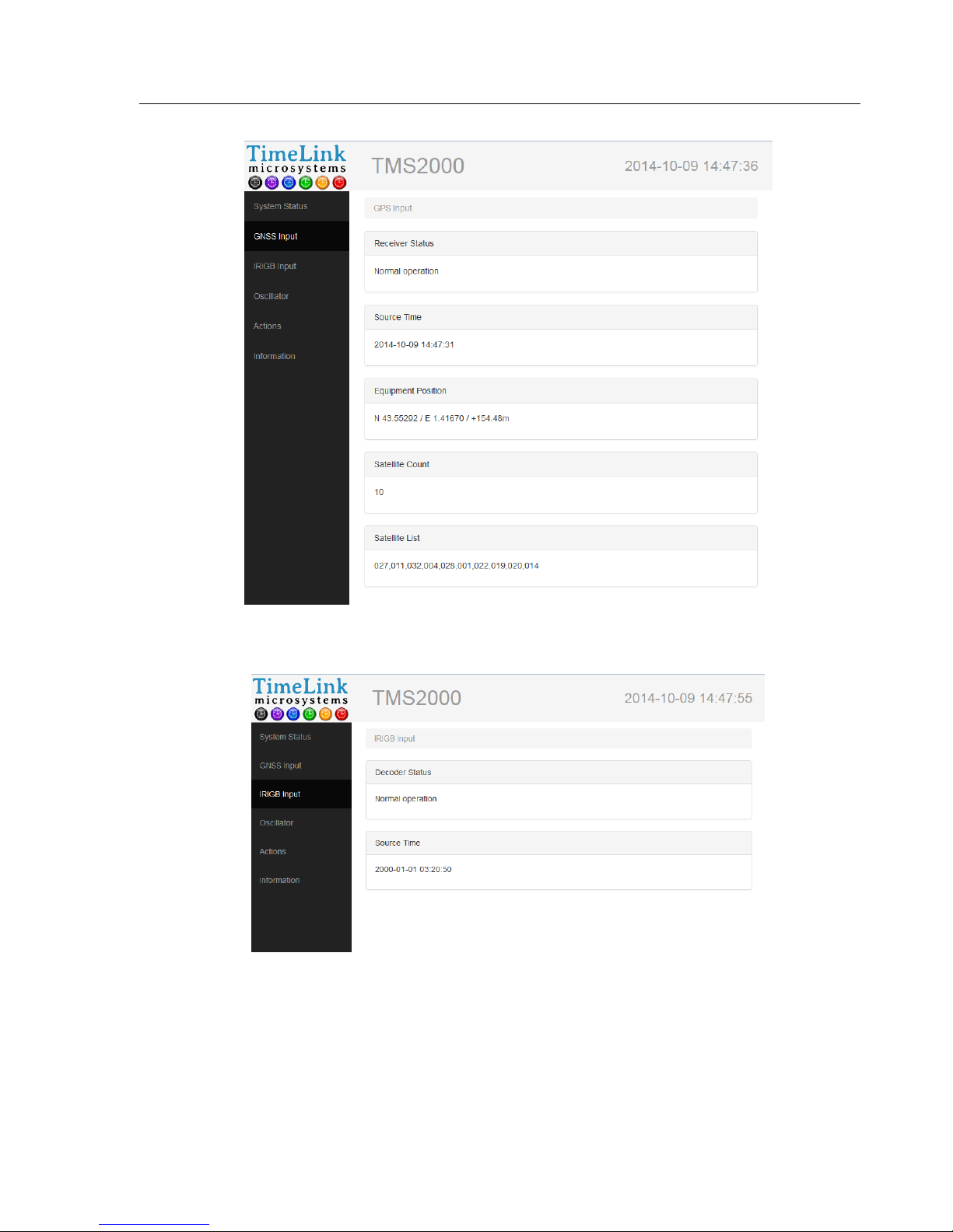
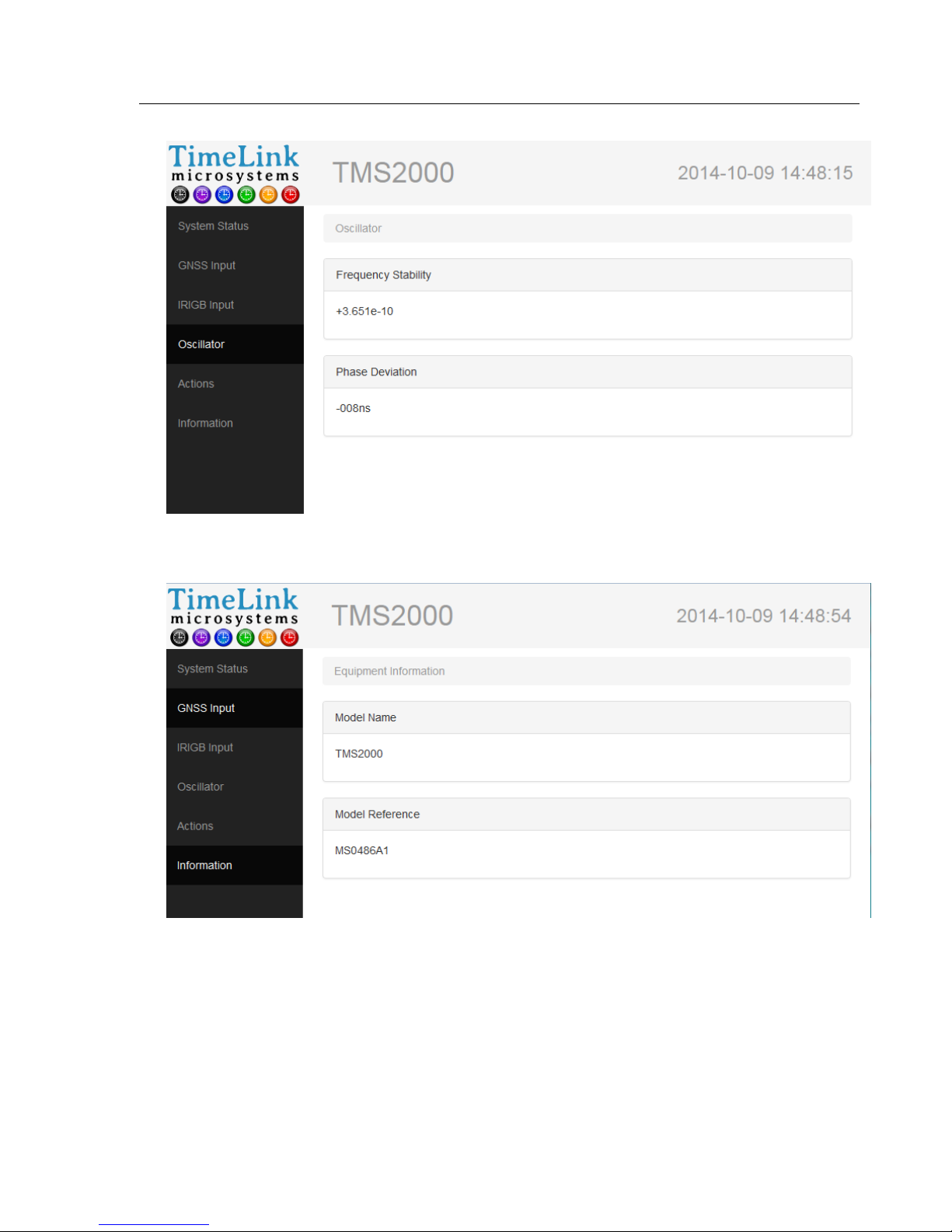
The screenshots below show the outline of the pages as they are displayed in a browser.
Homepage
Page 14
TMS2000
USER’S MANUAL
Reference :
MN0474
Date :
2015-01-07
issue :
A0
Page:
14/21
All rights reserved © TimeLink microsystems
GNSS screen
IRIGB screen
Page 15
TMS2000
USER’S MANUAL
Reference :
MN0474
Date :
2015-01-07
issue :
A0
Page:
15/21
All rights reserved © TimeLink microsystems
Oscillator screen
Information screen
Page 16
TMS2000
USER’S MANUAL
Reference :
MN0474
Date :
2015-01-07
issue :
A0
Page:
16/21
All rights reserved © TimeLink microsystems
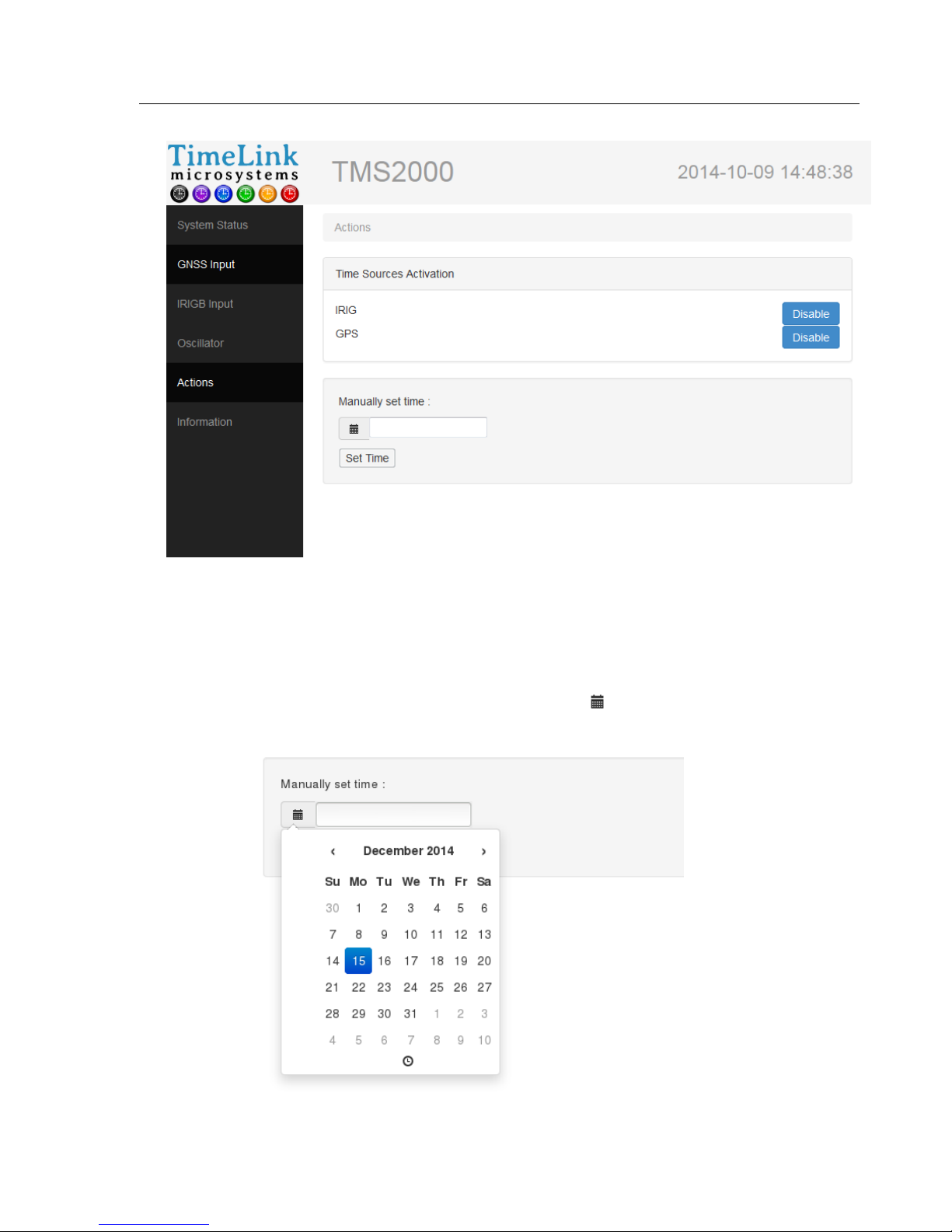
Actions screen
4.1.1. Setting time manually
The 'Actions' screen offers you the ability to set yourself the system time. For this, you need to disable all time
sources available on the device by clicking the "Disable" button in front of each of them.
Once deactivated sources, you can enter the time by clicking the icon . This opens a dialog box offering you to
first entry date:
Page 17
TMS2000
USER’S MANUAL
Reference :
MN0474
Date :
2015-01-07
issue :
A0
Page:
17/21
All rights reserved © TimeLink microsystems
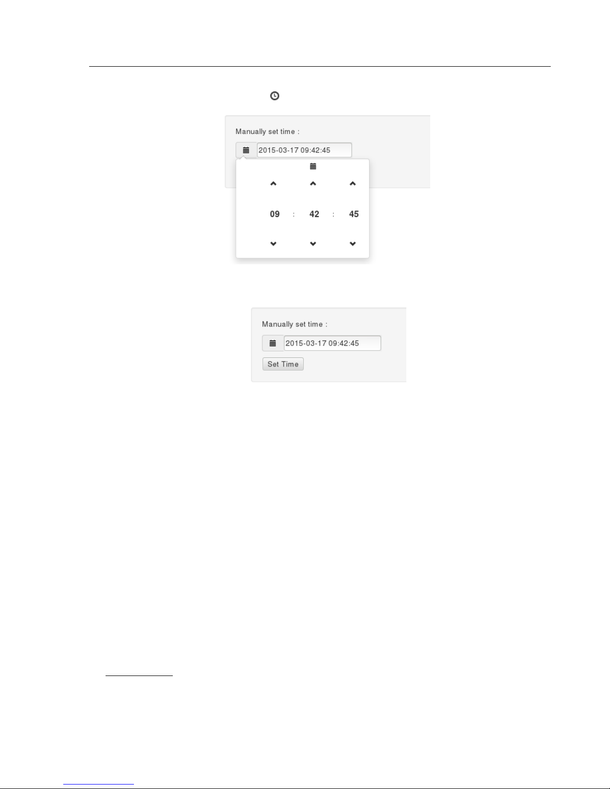
Once the new date selected, click the icon at the bottom of the dialog box to access the time entry:
After finishing input, you can close the dialog box by clicking outside of it, then click on "Set Time" to put the
equipment at the selected time:
4.2. UDP frame
A UDP frame can be sent to one or more recipients. The configuration of the recipient list is detailed in the section
referring to the system configuration.
The frame contains the following fields separated by ',':
• date and hour of the frame: 2014-09-15 12:00:00
• Time Quality Indicator QF5
• Frequency quality indicator: QF4
• value of the estimate of the frequency stability: -1.230e-11
• difference between the generated PPS and t UTC PPS: -007ns
• current value of the DAC of the oscillator: 0412437
• name of the time source that synchronizes equipment: GPS
• value of the GNSS status: C: 000: O
• value of the acquisition status of the IRIG-B signal: 0
• number and list of alarm codes: [0, NONE]
Example of frame:
2014-10-09 14:59:34,QT5,QF4,+3.610e-10,+008ns,0669564,GPS,C:100:O,0,[0,NONE]
Page 18

TMS2000
USER’S MANUAL
Reference :
MN0474
Date :
2015-01-07
issue :
A0
Page:
18/21
All rights reserved © TimeLink microsystems
Remarks:
The status of GNSS has 3 information’s separated by the character ':':
• antenna status: 'C' for connected, 'N' for not connected, 'S' for short circuit
• value of the survey: from 000 to 100 (000 is not abnormal if the survey is off)
• status of decoding: 'O' for correct decoding, 'N' for incorrect
The status of the acquisition of the IRIG-B signal is a figure whose values are:
• 0: nominal acquisition
• 6: Signal decoding error
• 8: No Signal
Alarm List is equal to 'NONE' when it is empty; otherwise it contains a list of error code separated by:
':'.
The values following 'QF' or 'QT' indicate a figure from 0 to 5 corresponding to the following tables:
For the time:
Bars
accuracy
Corresponding status of the
equipment
0
> 10µs
Malfunction if steady.
(Normal at startup)
1
1µs to 10µs
2
1µs to 500ns
3
500ns to 100ns
4
100ns to 50ns
Nominal
5
< 50ns
Accuracy is a picture of the difference between the PPS generated by the equipment and the PPS issued by the
reference source.
For the frequency :
Bars
Stability
Corresponding status of the
equipment
0
> 1e-8
Malfunction if steady.
(Normal at startup)
1
1e-8 à 5e-9
2
5e-9 à 1e-9
3
1e-9 à 5e-10
Nominal
4
5e-10 à 1e-10
5
< 1e-10
Page 19

TMS2000
USER’S MANUAL
Reference :
MN0474
Date :
2015-01-07
issue :
A0
Page:
19/21
All rights reserved © TimeLink microsystems
5. MAINTENANCE
The maintenance on the equipment comes down to updating the software.
5.1. Updating the software
Important: The software update can only be performed by the user 'root' (cf. §3.3.2.4).
The software update is done using the tool '/ usr / bin / update' available on the equipment. Its use requires the
following:
• be copied to the SD card (s) file (s) to update.
• to connect via SSH or from the equipment console (after re-inserting the SD card and restarted the
equipment)
Use the tool '/usr/bin/update'
5.2. File for the update
The software update is performed by writing the binary file in the directory 'update' of the SD card in the
permanent memory of the processor.
To do so please type the following command from a command shell.
"/usr/bin/update -u /config/update/<file>"
Where <file> is the name of the binary file that contains the update to perform..
It is recommended to verify that the file you just flash is the same as your source. For that please enter the
following command:
"/ Usr / bin / update -c / config / update / <file>"
The result of this command will tell you if the files are identical.
If you see a message indicating that the files are different re-try again the two previous orders.
Note: If the update cannot be done it is likely that the flash memory of the processor may be damaged. It is then
necessary to return the equipment or just the module to Timelink microsystems for investigation.
As, no sensitive data are located on the data processor module, no data will be visible by Timelink microsystems.
5.3. Resetting the GNSS
To reset the GNSS it is necessary to connect in console or ssh on the equipment. Once connected type the
following command from a command shell:
"/ Usr / bin / coldStart"
While resetting the GNSS equipment will operate in free-running mode (not disciplined by GNSS) and at the end of
the reset it back to its nominal operation.
Note: It is recommended to re-start the equipment after this operation in order to have a better estimate of the
stability of the oscillator as the 'coldStart induces abnormal measures which temporarily affect this calculation.
Page 20

TMS2000
USER’S MANUAL
Reference :
MN0474
Date :
2015-01-07
issue :
A0
Page:
20/21
All rights reserved © TimeLink microsystems
6. ANNEXES
6.1. Changing the configuration files
The only configuration file that can be changed on these devices is the file 'user.ini'.
You can edit this file in two ways:
• from the equipment
• with a PC fitted with an SD card reader
6.1.1. Changing from equipment
To begin, please log into the system from the console port or from SSH access.
Once connected and logged into the system just use the editor 'vi' provided in the equipment to edit the file
'user.ini'.
Type 'vi /config/user.ini', change the values that can be changed, save the file and exit the editor.
After editing the file you must restart the device by typing 'reboot' for the new values to take effect.
6.1.2. Changing from a PC equipped with an SD card reader
To modify the file you must first stop the equipment, extract the SD card and insert it into the card reader on your
PC.
Use a text editor to edit the file 'user.ini' from your PC. Eject the card and insert it back into the device and restart
it.
Important note:
According to the editor used you must check that the encoding of line breaks are in UNIX format and not
WINDOWS otherwise you will not be able to read the file from the device (only LF, not CR, LF).
Page 21

TMS2000
USER’S MANUAL
Reference :
MN0474
Date :
2015-01-07
issue :
A0
Page:
21/21
All rights reserved © TimeLink microsystems
Summary of parameters values on the TMS2000.
Category
Parameter
Default value
Optional value
[NETWORK]
IP
192.168.10.190
MASK
255.255.255.0
MAC
According to serial number
(S/N) of the equipment
GW
192.168.10.254
BROADCAST
192.168.10.255
NAMESERVER
8.8.8.8
[NTP_SERVER]
ENABLE
Y VERSION
AUTO
NOTIME
NO_ANSWER
[IRIGB_IN]
ENABLE
Y CODE
2 YEAR
2014
[GPS]
UTC_OFFSET
16 [RM]
PUSH_TO
192.168.10.191:9000
Password 'maintenance'
tms2000
Password 'root'
tms2000
*** End of document ***
 Loading...