

Page 1

TMS1000
USER MANUAL
Reference : MN0482
Tous droits réservés © TimeLink microsystems
Release : A3
Date : 2017-09-04
Page 2

TMS1000
USER MANUAL
CHANGES IN THE DOCUMENT
Release DATE OBJECT of CHANGE
A1 2014-11-19 Initial version
A2 2014-12-15 Details concerning system update and manual date setup
A2_EN 2016-10-27 English version provided
A3_EN 2017-09-05 New password associated with LO665A2
Name-Title Date and Signature
Reference : MN0482 Date : 2017-09-04
Release: A3 Page: 2/18
Author Arnaud FERRARIS
Software Engineer - TimeLink microsystems
Approve by Jean-Claude POUYTES
Quality Manager - TimeLink microsystems
2014-11-19 / AF
2014-11-21 / JCP
Tous droits réservés © TimeLink microsystems
Page 3

TMS1000
USER MANUAL
Reference : MN0482 Date : 2017-09-04
Release: A3 Page: 3/18
TABLE OF CONTENT
1. GENERAL DESCRIPTION 4
1.1. FRONT AND BACK PANELS ........................................................................................................................... 4
1.2. FUNCTIONAL CHARACTERISTICS .................................................................................................................. 5
1.3. PHYSICAL CHARACTERISTICS ........................................................................................................................ 5
2. PREPARATION FOR USE 6
2.1. CONNECTIONS ............................................................................................................................................. 6
2.2. CONFIGURATION ......................................................................................................................................... 6
2.2.1. TMS1000 SETTINGS ................................................................................................................................ 7
3. GETTING STARTED 8
3.1. POWERING UP ............................................................................................................................................. 8
3.2. LEDS ............................................................................................................................................................. 8
3.2.1. LEDS AT STARTUP................................................................................................................................... 8
3.2.2. LEDS DURING OPERATIONS ................................................................................................................ 9
3.3. INTERFACES ................................................................................................................................................. 9
3.3.1. NTP SERVICE .......................................................................................................................................... 9
3.3.2. SSH ACCESS ............................................................................................................................................ 9
3.3.2.1. SYSTEM SOFTWARE UPDATE ..................................................................................................... 10
3.3.2.2. CHANGE PASSWORD ................................................................................................................. 10
3.3.2.3. RESTART OR STOP THE EQUIPEMENT ....................................................................................... 10
3.3.2.4. CHANGE TO USER 'root' ............................................................................................................ 10
3.3.3. SERIAL CONSOLE ACCESS ..................................................................................................................... 10
4. MONITORING 10
4.1. HTTP Server ............................................................................................................................................... 11
4.2. MANUAL TIME SETTING ............................................................................................................................ 13
4.3. UDP FRAME ............................................................................................................................................... 14
5. MAINTENANCE 15
5.1. SOFTWARE RELOADING ............................................................................................................................. 15
5.2. SOFTWARE UPDATE ................................................................................................................................... 16
5.3. GNSS RECEIVER RESET ............................................................................................................................... 16
6. APPENDIX 16
6.1. CONFIGURATION FILES EDITION ................................................................................................................ 16
6.1.1. EDITING FROM THE EQUIPEMENT ....................................................................................................... 16
1.1.1. EDITING FROM AN EXTERNAL SYSTEM ................................................................................................ 17
Tous droits réservés © TimeLink microsystems
Page 4
TMS1000
USER MANUAL
Reference : MN0482 Date : 2017-09-04
Release: A3 Page: 4/18
1. GENERAL DESCRIPTION
The TMS1000 is a GNSS disciplined NTP server.
1.1. FRONT AND BACK PANELS
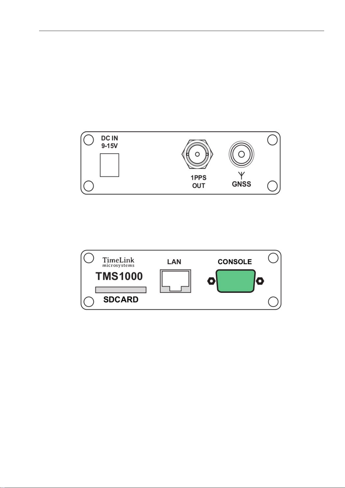
The front panel of the equipment includes the power supply connector, the GNSS antenna connector as well as the
1 PPS output.
Figure 1 – Front panel
The back panel of the equipment includes the control interfaces (console and SDCARD) and the network RJ45
connector.
Figure 2 – Back panel
Tous droits réservés © TimeLink microsystems
Page 5

TMS1000
USER MANUAL
Reference : MN0482 Date : 2017-09-04
The top panel includes four LEDS displaying the equipment status.
Figure 3 – Top panel
Release: A3 Page: 5/18
1.2. FUNCTIONAL CHARACTERISTICS
The table below summarizes the functional characteristics of the equipment.
Characteristics Types/Values
1PPS output Level : 0-5V, positive pulse, 50 Ω
Female BNC connector - Identification: "1PPS OUT"
Duration: 1ms, Period:1Hz
SDCard "Push-push" type connector on back panel – identification “SDCARD”
Power supply 12V DC adaptor (provided)
Consumption : ~3W / 12VDC
LAN/Network Ethernet 100 Mbps
RJ45 - Identification "LAN"
NTP service Port UDP 123, Client/Server mode (unicast)
Console SubD 9 pins connector, 115200 bauds, 8bits, 1 stop bit
SSH service Port TCP 22
HTTP service Port TCP 80
Remote monitoring UDP connections towards configurable IP/Ports
TMS1000 functional characteristics
1.3. PHYSICAL CHARACTERISTICS
The table below summarizes the physical characteristics of the equipment.
Tous droits réservés © TimeLink microsystems
Page 6

TMS1000
USER MANUAL
Reference : MN0482 Date : 2017-09-04
Release: A3 Page: 6/18
Characteristics Types/Values
Size Width 105mm – Height 33mm – depth 167mm
Weight 418g
TMS1000 physical characteristics
2. PREPARATION FOR USE
Before using the equipment, it is necessary to perform the operations described below.
2.1. CONNECTIONS
The following connections must be made:
Connect the equipment to the DC power via the supplied DC cord.
Connect the GNSS antenna cable to the antenna input of the equipment.
Connect the equipment to the remote management network ("LAN" connector) with a RJ45 network
cable.
Important: Power on the equipment only after all connections has been made.
2.2. CONFIGURATION
Configuration parameters must be setup with consistent values to allow proper use of the equipment. Those settings
are in files located within an SDCard inserted in the back of the equipment.
The parameters available to the user are located in the "user.ini" file. This file is within the SDCard directory
“TMS1000” when mounted using a PC, and within “/config” when accessed through remote access (console or
network).
The following table lists the parameters by functional chapter the same way they are laid out within the configuration
file. The procedure to change the settings is described in an appendix to this document.
Important: Please do not modify files other parameters than those listed below under penalty of breaking the
equipment’s operation, except if the support staff of Timelink microsystems invites you to do so.
Tous droits réservés © TimeLink microsystems
Page 7

TMS1000
USER MANUAL
Reference : MN0482 Date : 2017-09-04
Release: A3 Page: 7/18
2.2.1. TMS1000 SETTINGS
These settings are located in the 'TMS1000/user.ini' file of the SDCARD.
Section [NETWORK]
Name Description Availability Default value Accepted values
IP IP V4 address of the
equipment
MASK Subnet mask of the
network on which the
equipment is connected
MAC MAC address of the
equipment
GW IP V4 address of the
default gateway
BROADCAST IP V4 broadcast address Optional 192.168.10.255 Any compliant IP V4
NAMESERVER IP V4 address of the name
server
Section [NTP_SERVER]
Name Description Availability Default value Accepted values
ENABLE Activate/deactivate the
NTP server
VERSION NTP protocol version to
use in replies
Mandatory 192.168.10.190 Any compliant IP V4
address
Mandatory 255.255.255.0 Any compliant subnet
mask
Mandatory Attributed
according to serial
number
Optional but
recommended
Optional 8.8.8.8 Any compliant IP V4
Mandatory Y Y or N
Mandatory AUTO
192.168.10.254 Any compliant IP V4
Any compliant MAC
address. Should normally
not be modified.
address
broadcast address
address
V3: indicates version 3
packet
V4: indicates version 4
packet
AUTO: adapt itself to the
requestor
NOTIME Behavior when unable to
get a consistent time
Section [GPS]
Name Description Availability Default value Accepted values
UTC_OFFSET Offset between GPS and
UTC time
Tous droits réservés © TimeLink microsystems
Mandatory NO_ANSWER
Mandatory 18
NO_ANSWER: do not
answer to NTP requests
LEAP: the NTP packet
contains the ‘LEAP’ flag,
indicating the server
does not provide a
consistent time
Page 8

TMS1000
USER MANUAL
Reference : MN0482 Date : 2017-09-04
Release: A3 Page: 8/18
Section [RM]
Name Description Availability Default value Accepted values
PUSH_TO IP V4:Port addresses of
the UDP frame recipients
Note: other parameters in the “user.ini” file must not be modified without guidance from Timelink microsystems.
Those parameters are listed right after the following warning:
#-----------------------------------------------------------------------#
# >>>> DO NOT MODIFY PARAMETERS UNDER THIS LINE <<<<
#-----------------------------------------------------------------------#
Mandatory 192.168.10.191:9000
List of commaseparated ‘IP:Port’
values
3. GETTING STARTED
3.1. POWERING UP
The equipment starts when the power is applied to the unit. There is no ON/OFF switch.
Notes:
1. During the boot sequence, the top panel LEDS are switched off during 15 seconds after power is applied.
2. Because of the very low consumption, following power off, one must wait 30 seconds before powering on
again. Otherwise a corrupted boot may occur.
3.2. LEDS
3.2.1. LEDS AT STARTUP
During the boot sequence, LEDS displays boot progress or an error code. Below is the summary of the different
options.
ON GNSS SYNC ALARM Description
Yellow Off Off Off SDCard mounting
Red Red Red Red SDCard missing or not seen
Green Yellow Off Off SDCard configuration reading
Red Off Off Red Network configuration error (IP address not defined)
Off Red Off Red Network configuration error (subnet mask not defined)
Off Off Red Red Network configuration error (MAC address not defined)
Green Green Yellow Off Network services starting
Green Green Blue Off Network services configuration (first boot only)
Green Green Green Yellow Application starting
Green Green Green Green Boot completed
Yellow Yellow Yellow Red Application did not start
Tableau 1 – LEDS during boot sequence
Tous droits réservés © TimeLink microsystems
Page 9

TMS1000
USER MANUAL
3.2.2. LEDS DURING OPERATIONS
LED Color Description
ON White System started
GNSS Red No GNSS source
Yellow The time source is available but excluded
Green The time source is operational and selected as the reference time source
Off GNSS source is not activated
SYNC Red Not GNSS synchronized
Green GNSS synchronized
ALARM Green No alarm ( Information message may be displayed)
Yellow At least one Warning Alarm type
Red At least one Error Alarm type
Reference : MN0482 Date : 2017-09-04
Release: A3 Page: 9/18
Tableau 2 – LEDS during operations
3.3. INTERFACES
Below interfaces are available:
1 PPS signal output
1 Ethernet 100Mbits connector
1 SDCard Reader
A 4 LEDS display
Several services are available on the Ethernet interface:
IP v4 NTP service
IP v4 SSH
HTTP server
UDP v4 server
3.3.1. NTP SERVICE
This service allows synchronizing an NTP client. The generated time is the one calculated by the equipment based
on one of the source connected to the equipment.
The NTP server is NTPV3 and V4 compliant; depending on its configuration whenever no reliable time is available it
can either not answer or answer with the LEAP flag.
3.3.2. SSH ACCESS
This service allows to remotely connecting to the equipment in secure mode through a network.
Only the 'maintenance' user is authorized to connect to the equipment. After a successful connection, a shell is
opened. Being a maintenance mode, the user must take care of its actions as they can result in the equipment no
longer being able to serve its primary functions.
Tous droits réservés © TimeLink microsystems
Page 10

TMS1000
USER MANUAL
Reference : MN0482 Date : 2017-09-04
Release: A3 Page: 10/18
The following commands are available:
update the software
modify the password of a user
restart or stop the equipment
connect as 'root'
The default password for both accounts is 'timelink'.
3.3.2.1. SYSTEM SOFTWARE UPDATE
The system software update is done using the provided 'update' tool. See the Maintenance section for the
procedure.
3.3.2.2. CHANGE PASSWORD
To change the password for a user, use the command 'passwd <user>'. The system will ask for the new
password and it will be written in encrypted format in a file on the SDCard.
Note:
The maintenance user password must be by the standard password rules as displayed when requested.
The root user can bypass the standard password rules.
3.3.2.3. RESTART OR STOP THE EQUIPEMENT
These functions allows for securely restart or stop the equipment. The user must first log in as 'root'.
To restart, use the 'reboot' command; to stop, use 'poweroff'.
After a 'poweroff' the equipment can be switched off.
3.3.2.4. CHANGE TO USER 'root'
The command below allows a user to change to user ‘root’:
Type '/tools/su' and enter the 'root' password.
3.3.3. SERIAL CONSOLE ACCESS
Access to the system can also be made from the Console port by connecting a terminal emulator. Use the following
configuration:
baud rate 115200
8 bits, 1 stop bit, no parity
After logging in with the login/password used to gain SSH access, a shell is opened. The same commands as those
described in the SSH chapter can be issued.
4. MONITORING
The equipment can be monitored through the integrated Web server, SNMP or by receiving a UDP frame
containing operation information about the equipment.
Tous droits réservés © TimeLink microsystems
Page 11
TMS1000
USER MANUAL
4.1. HTTP Server
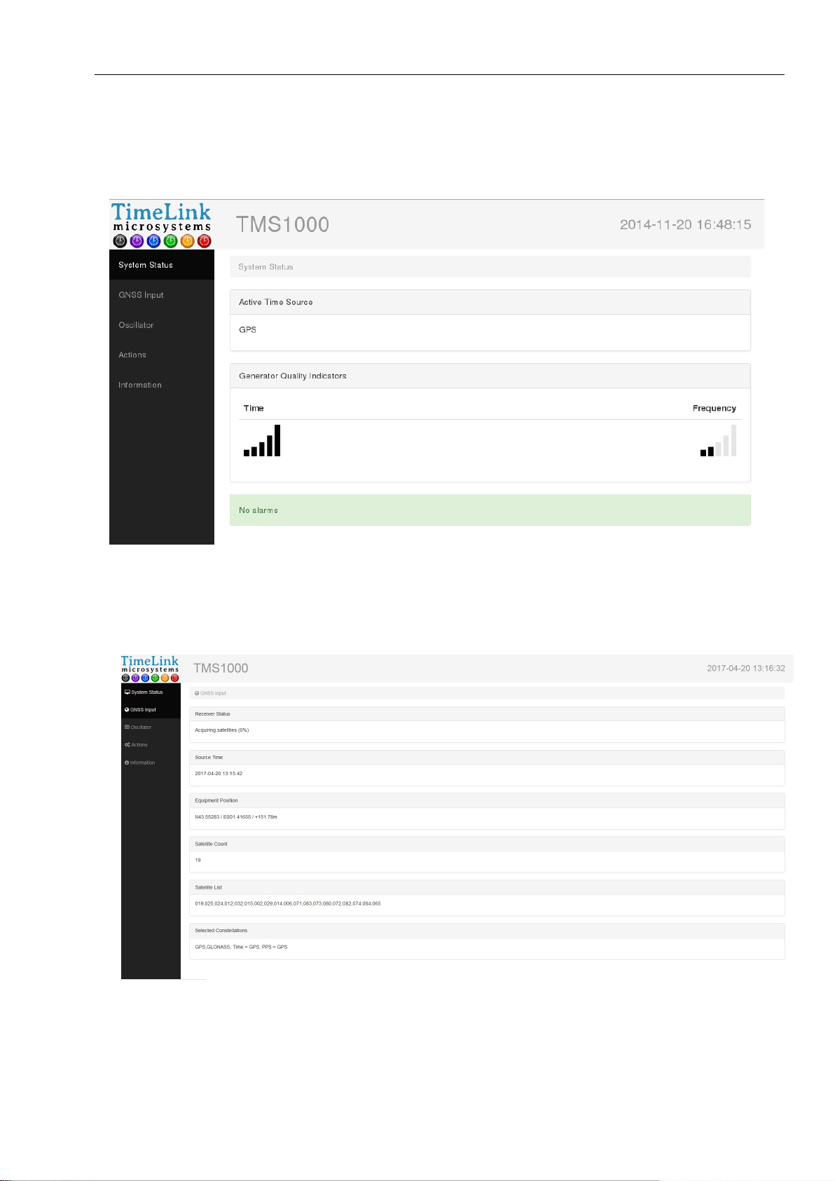
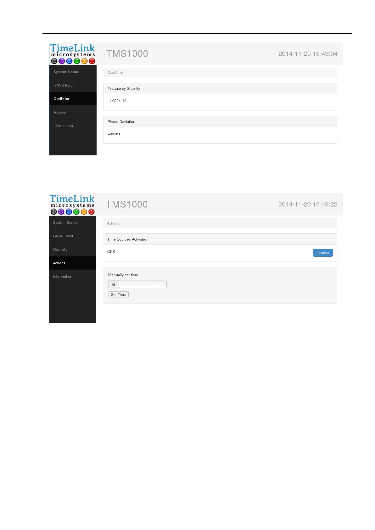
The integrated http server uses port 80. The following screenshots give a preview of the pages as they appear
in a browser:
Reference : MN0482 Date : 2017-09-04
Release: A3 Page: 11/18
Default screen
GNSS screen
Tous droits réservés © TimeLink microsystems
Page 12
TMS1000
USER MANUAL
Reference : MN0482 Date : 2017-09-04
Release: A3 Page: 12/18
Oscillator screen
Actions screen
Tous droits réservés © TimeLink microsystems
Page 13
TMS1000
USER MANUAL
Reference : MN0482 Date : 2017-09-04
Release: A3 Page: 13/18
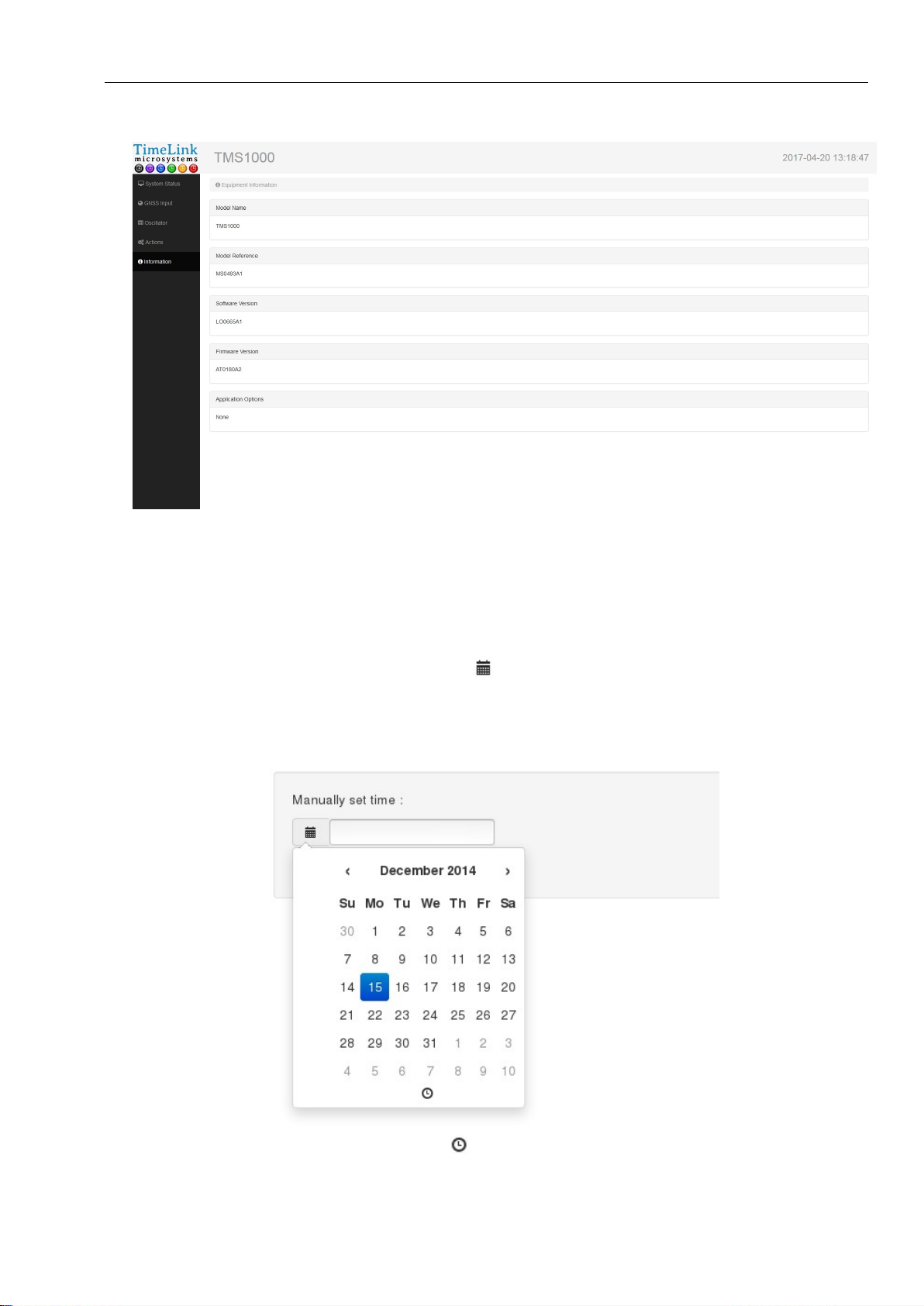
Information screen
4.2. MANUAL TIME SETTING
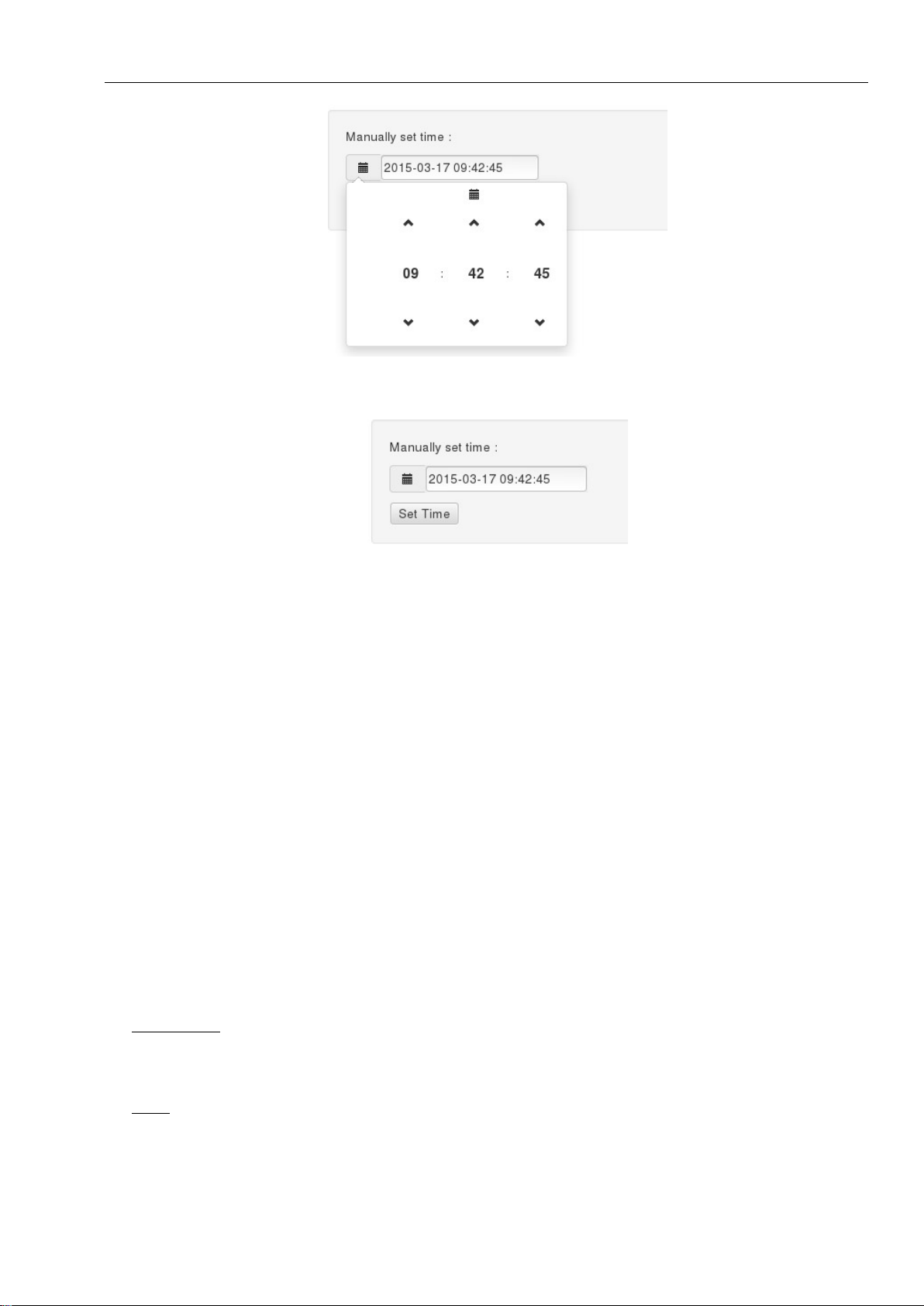
On the “Actions” screen, you can manually set the system time. First, you have to disable all the available time
sources by pressing the “Disable” button in front of each source. Once each time source has been disabled, you
can enter the current date and time by clicking on the icon, which opens a dialog allowing you to define the new
date:
Once the new date has been selected, click on the icon, on the bottom of the dialog, to be able to set the time:
Tous droits réservés © TimeLink microsystems
Page 14
TMS1000
USER MANUAL
Reference : MN0482 Date : 2017-09-04
Release: A3 Page: 14/18
Once the date and time have been selected, close the dialog by clicking outside of it, then press the “Set Time”
button to update the system time:
4.3. UDP FRAME
A UDP frame can be automatically sent, each second, to one or several recipient systems. The corresponding
configuration is described along with the system’s configuration (‘[RM]’ section).
The frame contains the following fields, separated by ‘,’:
Frame date and time: 2014-09-15 12:00:00
Time quality indicator: QT5
Frequency quality indicator: QF4
Estimated frequency stability value: -1.230e-11
Offset between generated PPS and UTC: -007ns
Current value of the oscillator’s DAC: 0412437
Name of the time source used for synchronizing the equipment: GPS
GNSS receiver status: C: 000: O
Count and list of currently active alarms: [0,NONE]
Frame sample:
2014-10-09 14:59:34,QT5,QF4,+3.610e-10,+008ns,0669564,GPS,C:100:O,[0,NONE]
Notes:
The GNSS receiver status contains 3 fields separated by ':':
Antenna status: connected ('C'), not connected ('N') or shorted ('S')
Survey progress: value between 000 to 100 (000 may be a normal value if survey is disabled)
Tous droits réservés © TimeLink microsystems
Page 15

TMS1000
USER MANUAL
Reference : MN0482 Date : 2017-09-04
Release: A3 Page: 15/18
Decoding status: decoding can be successful ('O') or incorrect ('N')
The alarms list equals 'NONE' when no alarm is active; otherwise, it contains a list of alarm codes separated by ':'
(see §6.2 for a full list of alarm codes).
'QF' and 'QT' are followed by a single digit between 0 and 5, see below for the corresponding status:
QT:
Bars Precision Equipment state
0 > 10µs
1 1µs to 10µs
2 500ns to 1µs
3 100ns to 500ns
4 50ns to 100ns Normal
5 < 50ns
Precision is an image of the phase difference between the internal generated 1PPS and the 1PPS of the time
source.
Indicates a problem in steady
state.
(Normal during startup)
QF :
Bars Stability Equipment state
0 > 1e-8
1 1e-8 to 5e-9
2 5e-9 to 1e-9
3 1e-9 to 5e-10
5 < 1e-10
Indicates a problem in steady
state.
(Normal during startup)
Nominal 4 5e-10 to 1e-10
5. MAINTENANCE
Maintenance operations are limited to software update.
5.1. SOFTWARE RELOADING
To be able to execute the update procedure you must be logged in as the 'root' user. See the section indicating
how to proceed.
Software update is done by using the provided tool: '/usr/bin/update'. Use it as follow:
Copy on the SDCard the file(s) to update.
Re-insert the SDCard and restart the equipment
Open a shell by connecting with SSH or the Console
Execute '/usr/bin/update'
Tous droits réservés © TimeLink microsystems
Page 16

TMS1000
USER MANUAL
Reference : MN0482 Date : 2017-09-04
Release: A3 Page: 16/18
5.2. SOFTWARE UPDATE
The software update is made by storing the binary file contained in the 'update' directory of the SDcard in the
FLASH memory of the processor module. If a new binary file is provided by Timelink microsystems, please copy it
first in the SDCard in the /update directory.
To proceed, type the following command in a command shell.
"/usr/bin/update -u /config/update/<filename>"
<Filename> is the name of the binary file which contains the new software.
It is highly recommended to verify that the update was fully successful. To proceed, type the command
"/usr/bin/update -c /config/update/<fichier>"
The resulting information will indicate if the updated flash content and the file are identical. If not, try again to
make the update.
Note: if the update fails, the flash memory of the processor module may have been damaged. It will be necessary
to return the equipment, or only the processor module, to TIMELINK microsystems for investigation.
No sensible user data are stored on the processor module so your data will not be visible to the manufacturer.
5.3. GNSS RECEIVER RESET
To reset the GNSS it is necessary to be connected on the console or in Ssh on the equipment. When connected
type the following command from a shell:
"/usr/bin/coldstart"
During the GNSS reset the equipment remains operational but not disciplined to the GNSS. At the end of the GNSS
reset the equipment resumes to its nominal behavior.
Note: It is recommended to restart the equipment at the end of a GNSS reset to have better frequency stability
estimation because the reset induces abnormal measures that temporarily affect this estimation in a negative way.
6. APPENDIX
6.1. CONFIGURATION FILES EDITION
The only configuration file that can be modified by the user on this equipment id the 'user.ini' files.
Two means are available to modify the file:
from the equipment itself
from a PC equipped with a SDCard reader
6.1.1. EDITING FROM THE EQUIPEMENT
First, log in from a Console or SSH.
Once connected, use the 'vi' editor provided in the equipment.
Type 'vi /config/user.ini', modify the values, save the file and exit from the editor.
Once the modification of the file has been done, restart the equipment by typing 'reboot' for the new values to
take effect.
Tous droits réservés © TimeLink microsystems
Page 17

TMS1000
USER MANUAL
Reference : MN0482 Date : 2017-09-04
Release: A3 Page: 17/18
1.1.1. EDITING FROM AN EXTERNAL SYSTEM
Before file modification, stop the equipment, remove the SDCard and insert it in the SDCard reader of a PC. Use a
text editor to modify the 'user.ini' file. Then remove the SDCard and insert it back in the equipment. Then power
on the equipment.
Important note:
Depending on the used text editor, verify than the encoding of the end of lines are in the UNIX format (only LF) and
not in the WINDOWS format (CR + LF). A bad encoding will lead to an unreadable file in the equipment. Text editor
'Notepad++' is a good choice for updating configuration files.
Tous droits réservés © TimeLink microsystems
Page 18

TMS1000
USER MANUAL
Reference : MN0482 Date : 2017-09-04
Release: A3 Page: 18/18
Summary of TMS1000 parameters
Section Parameter Default value Operational value
[NETWORK] IP 192.168.10.190
MASK 255.255.255.0
MAC
GW 192.168.10.254
BROADCAST 192.168.10.255
NAMESERVER 8.8.8.8
[NTP_SERVER] ENABLE Y
VERSION AUTO
NOTIME NO_ANSWER
[GPS] UTC_OFFSET 16
[RM] PUSH_TO 192.168.10.191:9000
Password 'maintenance' timelink
Password 'root' timelink
Depends on equipment serial
number
*** End of document ***
Tous droits réservés © TimeLink microsystems
 Loading...