

Page 1

Operating instructions
for Shukuma Motion Controller
Getting started with the SMC
This document describes the means of interacting with the controller through the user interface, and how to use the main
controller.
Included with your SMC:
• controller
• power cable
• camera cable
• velcro
Buttons There are five pushbuttons. Each button is multifunctional.
The four black buttons are “LEFT”, “RIGHT”, “UP” and “DOWN” while the red button to the lower left is the “ENTER”
button.
ENTER:
• Brings up the main menu, or selects a menu item.
• Saves the current value being edited
• Exits manual motor control
UP:
• Selects the menu item directly above
• Increases the value of the currently selected item
• Increases motor speed (manual motor control)
DOWN:
• Selects the menu item directly below
• Decreases the value of the currently selected item
• Decreases motor speed (manual motor control)
LEFT:
• Moves input selection left (main screen only)
• Moves current motor left (manual motor control)
RIGHT:
• Moves input selection right (main screen only)
• Cancels value input (when changing the value of a selected item)
• Moves current motor right (manual motor control)
www.timelapsesa.co.za | info@timelapsesa.co.za | +27 82 331 4438 1
Page 2

Menus and editing values
When on the Main Screen, pressing the Enter button will draw the main menu.
Pressing “ENTER” on any menu item will either draw the sub-menu selected or, if the item selected is an input, it will be
displayed for editing.
When a value for editing is displayed, you may use “UP” and “DOWN” to alter the value. If you wish to save the value,
simply press “ENTER” again. To exit the editor without saving, press the “RIGHT” button and the original value will be
restored.
The “RIGHT” button also functions as the “back” button, allowing one to go back one level from any menu, or return to
theMain Screen from the top-level menu.
To increase or decrease a number, you can simply hold “UP” or “DOWN” to continue to increase or decrease the value for
as long as you hold it down. The longer the button is held, the faster it increases or decreases a value. In this manner,
you may easily enter large numbers.
Interacting with the Controller
The SMC is designed to be simple to use, and to let you quickly input the most important parameters during a shoot.
The Main Screen
The Main Screen provides an overview of the current status and also allows for quick modification of key operating
parameters. This screen has the following layout:
On the first line we have the current status (On or Off), the intervalometer timing (3s), and a count of shots fired since
turned on ([15]).
The second line displays the direction and speed for each motor,with motor 1 on the left, and motor 2 on the right.
Pressing “RIGHT” will advance through the values that can be changed directly from the main screen:status, timing,
direction and speed of each motor.
When a particular value is displayed with a flashing cursor on it, you can change the value using “UP” and “DOWN”.
www.timelapsesa.co.za | info@timelapsesa.co.za | +27 82 331 4438 2
Saving Input Values Permanently
When editing certain values (such as RPM for a motor axis, interval time, etc.) they are automatically saved to permanent memory
for you. In this way, you will not have to make the same changes between re-start. The values which are saved permanently are
indicated in their appropriate documentation. To wipe out permanent memory, and reset to default values, choose the ‘ResetMem’
option in the Main Settings menu.
Please note: direction and speed of a given axis are designed to be changed regularly, and are not saved to permanent memory.
ON / OFF
To gg l e w it h u p / do w n b ut t on s
Increase / Decrease Interval
ON / OFF
To gg l e w it h u p / do w n b ut t
Page 3
Navigate through the controller
1. Manual Move
To move or position the cart and scope at a location
• 1.1) Axis 1 - UP / DOWN (to control speed) L / R (to control direction) p....04
• 1.2) Axis 2 - Info is the same as Axis 1 but control axis 2 p....04
• 1.3) Scope - Move Merlin manually (also see #5) p....05
2. a) Axis 1
Fine tune adjustments on the motor for motor port #1
• 2.1) Ramp Shots - ramp in/out of shots p....05
• 2.2) Lead In - # of shots before move starts p....06
• 2.3) Lead Out - # of shots after move p....06
• 2.4) RPM - RPM is pre set. Should you change to a different motor, dial
in RPM of specific motor p....07
• 2.5) Angle - Adjust the angle of the dolly p....07
• 2.6) Calibrate - Calibrate the controller p....07
• 2.7) Cal. Constant - Adjusting the calibration p....08
• 2.8) Slow Mode IPM - Information to be added p....09
• 2.9) Dist. per Rev - Setting output drive distance p....09
• 2.10) Min Pulse - Heavy loads or weak motors p....09
2. b) Axis 2
Fine tune adjustments on the motor for motor port #2
• 2.1) Ramp Shots - ramp in/out of shots p....09
• 2.2) Lead In - # of shots before move starts p....09
• 2.3) Lead Out - #of shots after move p....09
• 2.4) RPM - RPM is pre set. Should you change to a different motor, dial
in RPM of specific motor p....09
• 2.5) Angle - Adjust the angle p....09
• 2.6) Calibrate - Calibrating the controller p....09
• 2.7) Cal. Constant - Adjusting calibration p....09
• 2.8) Slow Mode IPM - Information to be added p....09
• 2.9) Dist. per Rev - Setting output drive distance p....09
• 2.10) Min Pulse - Heavy loads or weak motors p....09
Notes:
• You may change any value when the shoot is running — it will take effect immediately.
• Pressing “LEFT” will back up one setting on the screen
• Pressing “ENTER” at any time when on the main screen will bring up the Main Menu. and speed of a given axis are
designed to be changed regularly, and are not saved to permanent memory.
www.timelapsesa.co.za | info@timelapsesa.co.za | +27 82 331 4438 3
Page 4

3. Camera
Adjust settings on controller that involves and controls the camera
• 3.1) Interval Sec - Configuring camera control p....10
• 3.2) Max Shots - Setting the number of frames to take p....10
• 3.3) Exp. Time ms - Controlling exposure with SMC p....11
•3.4) Exp. Delay ms - Controlling exposure with camera p....11
• 3.5) Focus Tap ms - AF, focus tap, shoot in live view p....12
• 3.6) Shutter + Focus - Focus with shutter p....12
•3.7) Repeat - Mirror Up and bracketing p....12
• 3.8) Repeat Delay - Mirror Up and bracketing p....12
4. Settings
Adjust settings for the controller
• 4.1) Motor Disp - Choose speed value (cm, inch, %) p....13
• 4.2) Motor S1 Mod - Choose between modes (Continuos, Interleaved) p....14
• 4.3) Backlight - Backlight auto off p....15
• 4.4) Auto Dim (sec) - LCD Brightness p....15
• 4.5) Blank LCD - Disable the LCD p....15
• 4.6) I / O 1 - Using remote inputs and outputs p....16
• 4.7) I / O 2 - Using remote inputs and outputs p....16
• 4.8) Metric Disp. - Turn ON/OFF cm display p....17
• 4.9) Reset Men - Reset to defaults p....17
• 4.10) Scope - Enable scope control p....17
• 4.11) Cal. Spd low - Setting the calibration targets p....17
•4.12) Cal. Spd hi - Setting the calibration targets p....17
• 4.13) Alt Out Pre ms - Using SMC to control other devices p....18
• 4.14) Alt Out Post ms - Using SMC to control other devices p....18
• 4.15) USB Trigger - Information to be added p....18
•4.16) Invert Dir - Information to be added p....18
• 4.17) Invert I / O - Information to be added p....18
5. Scope
Adjust speed for manual move on scope
• 5.1) Pan Man. Spd - Adjust the pan speed of manual move scope p....19
• 5.2) Tilt Man. Spd - Adjust the tilt speed of manual move scope p....19
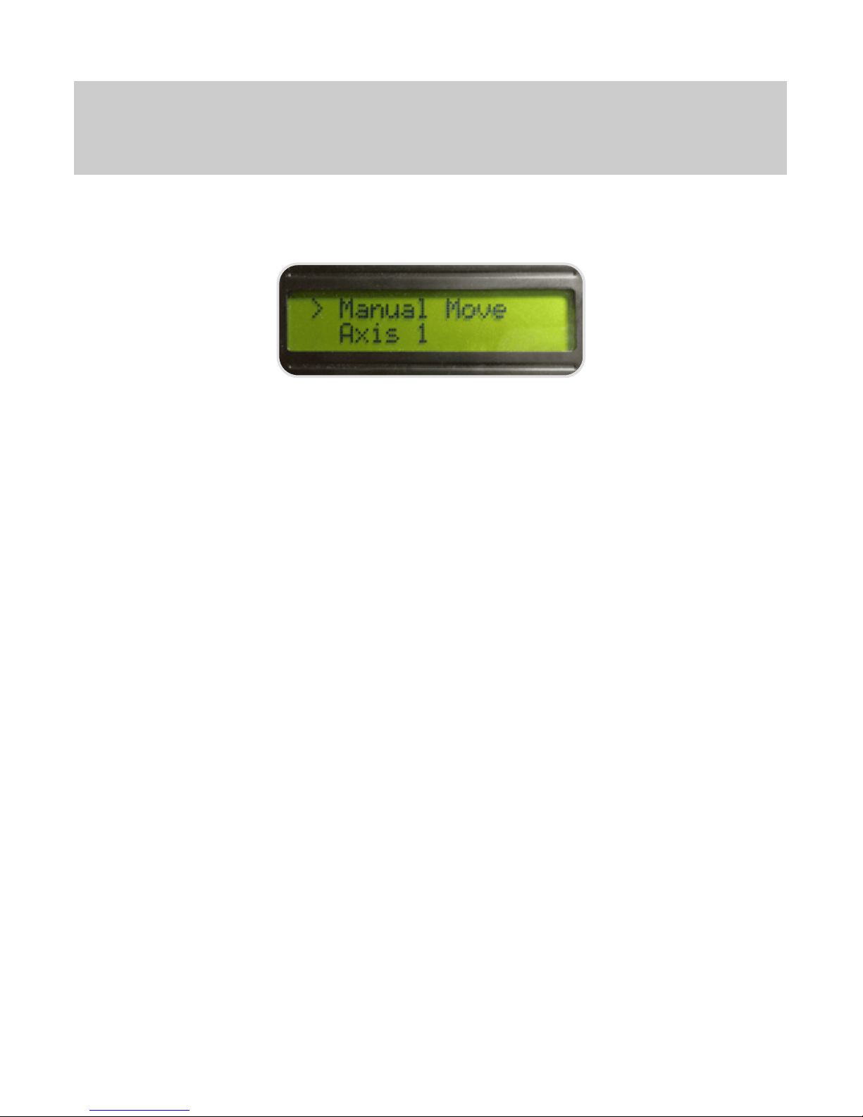
1. MANUAL MOVE
1.1 / 1.2 Manual motor control
Manual Motor Control can be used to position the cart on the rail between moves.
Using Manual Control
While on the manual control screen, you can use “UP” and “DOWN” to adjust the speed of the motor, up to its max speed,
and by holding “LEFT” or “RIGHT” down, the motor will move in the given direction at the specified speed until the button
is released. To exit the manual control screen, press “ENTER”, then back until in the main screen.
Notes:
• In manual control mode, the available speeds at which the cart will move will range from about 50% to 100% of full speed,
at lower speeds the cart may not move.
www.timelapsesa.co.za | info@timelapsesa.co.za | +27 82 331 4438 4
Page 5

Actions:
1. “ENTER” to enter the main menu
2. Select Manual Move and press “ENTER”
3. “UP” or “DOWN” to select the desired axis, and press “ENTER”
4. “UP” or “DOWN” to set the desired speed
5. Hold “RIGHT” or “LEFT” to move in the desired direction
6. “ENTER” to exit the manual control screen
7. “RIGHT” to return to the main menu
1.3 Manually move the Merlin
Once you have enabled scope control, you will now have a new option available in the manual control screen labeled
scope. This option enables you to control both axes of the Merlin from a single screen.
Inside the scope manual control screen, use [left] to cause the pan (yaw) axis to start moving left, and [right] to cause the
pan axis to start moving right. Pressing either button again will cause the motion to stop. [up] and [down] cause the tilt
(pitch) axis to move either up or down, again, pressing either a second time will stop movement.
Press [enter] to exit this screen and return to the main manual control screen.
You can configure the speeds at which the pan and tilt axes move in the scope manual control screen by accessing the
Main Menu->Scope menu, and configuring the desired manual speed, from 0.1 deg/minute, to 1,440 deg/minute.
Actions:
1. [Enter] to enter the main menu
2. [Down] to select Manual and press [Enter]
3. [Down] to select Scope, and press [Enter]
4. [Up], [Down], [Left], and [Right] to position the Merlin
5. [Enter] to exit the manual control screen
6. [Right] to return to the main menu
2. a) AXIS 1
2.1 Ramping or feathering into moves
The SMC motion controller can “feather” or ramp into and out of moves causing moves to start slowly and get faster
within the video, providing a nice accelerating or decelerating effect. It does this by altering the distance moved between
shots, or the speed moved, starting with no speed and ramping up to your desired speed over a configurable number of
frames.
Additionally, a lead-in or lead-out can be used to add a static period before or after a motor’s movements, adding to your
ability to create the shot you want.
Configuring Ramping
A ramp into or out of a movement is done by changing the speed or distance moved based on the number of frames that
have been exposed. For example, I can set the ramp value for an axis to 25 frames, and at 25FPS output video it would
take one second for the motion in the output video to come to full speed. This is achieved by starting the motor at no
speed, and then increasing the speed just enough to match the desired output speed at the right interval to reach full
speed at the desired frame as specified in the ramp value.
If you also configure the max shots parameter for the camera, the SMC will automatically ramp down the motor to zero
speed so that motion completes when the max shots count is reached.
To understand how ramping will affect your output video, take the following parameter values:
Output video = 25 frames per second
Max shots = 250 (10 seconds)
Ramp rate = 25
Axis speed = 30%
Notes:
• Ramp settings for a particular axis are saved between power-off cycles.
www.timelapsesa.co.za | info@timelapsesa.co.za | +27 82 331 4438 5
Page 6

The following will happen in the output video:
For one second, the motion will accelerate to full speed
For eight seconds, the motion will run at full speed (30%)
For one second, the motor will decelerate to no speed
This illustrates how ramping is achieved and the end result in your output video.
Actions:
1. “ENTER” to enter the main menu
2. “DOWN” to select Axis x and press “ENTER”
3. “DOWN” to select Ramp and press “ENTER”
4. “UP” or “DOWN” to input the number of frames to reach full speed
5. “ENTER” to save or “RIGHT” to abort without saving
6. “RIGHT” to return to the main menu
7. “RIGHT” to return to the main screen
8. “RIGHT” as many times needed to select the desired axis speed
9. “UP” and “DOWN” to adjust the desired speed
10. “LEFT” to the On/Off control
11. “UP” to start the program running
Once the program starts running, the speed will set its self to zero for any axis with a ramp value configured. If you stop
the program running before it reaches full speed, it will now see the current speed as the desired speed, and you will
have to increase it back to your original value.
2.2 / 2.3 Using a lead-in or lead-out
A lead-in defines a period of time, in frames from the beginning of the shoot, that the motor should not move. Conversely,
a lead-out defines the period of time from the end of the shoot that the motor should not move. Each axis can have its
own lead-in and lead-out times defined — however, to function, a ramp value must be set for that axis as well. Leads are
executed through the ramping/feathering function of the controller, by simply preventing it from starting a ramp before a
certain number of frames have passed (in the case of a lead-in), or reducing the overall number of frames counted before
ramping all the way down to zero (in the case of a lead-out).
As with ramping/feathering, a lead-out is only used if the max shots parameter has been set, and therefore the controller
can determine when to start reducing speed.
To help clarify this function, we’ll use the same parameters from the ramping example, and add a lead-in and lead-out.
Take the following parameter values:
Output video = 25 frames per second
Max shots = 250 (10 seconds)
Ramp rate = 25
Lead-in = 25
Lead-out = 25
Axis speed = 30 %
The following will happen in the output video:
For one second, no movement will occur
For one second, the motion will accelerate to full speed (0% - 30%)
For six seconds, the motion will run at full speed (30%)
For one second, the motor will decelerate to no speed (30% - 0%)
For one second, no movement will occur
Actions:
1. “ENTER” to enter the main menu
2. “DOWN” to select Axis x and press “ENTER”
3. “DOWN” to select Lead-in or Lead-out and press “ENTER”
4. “UP” or “DOWN” to input the number of frames to lead in or out with
5. “ENTER” to save or “RIGHT” to abort without saving “LEFT”
Notes:
• The ramp value for each axis is controlled independently.
www.timelapsesa.co.za | info@timelapsesa.co.za | +27 82 331 4438 6
Page 7

2.4 Setting motor RPM
This setting allows you to input the Revolutions Per Minute of the motor you are controlling. This aids in determining the
max speed of the motor.
Do not use this setting to adjust performance of the motor under load! Calibrate the axis [5] instead.
Like most settings, the value is stored when powering off, and only needs to be changed when you change motors.
Actions:
1. “ENTER” to enter the main menu
2. “DOWN” to select Axis x and press “ENTER”
3. “DOWN” to select RPM and press “ENTER”
4. “UP” or “DOWN” to input the correct RPM for your motor
5. “ENTER” to save or “RIGHT” to abort without saving
2.5 Adjusting the angle of the dolly
When operating the dolly at an angle, and using Inches Per Minute (IPM) speed input, you will want to inform the
controller of the nearest angle of the track so that it can adjust based on the calibration for that angle. You may set the
angle of the dolly (or any other linear axis) in the Axis Configuration menu for the given axis. Three angle values are
possible: 0, 45, and 90. The 0 degree angle corresponds to the dolly being largely in parallel to the ground, 45 degrees
corresponds to the track being at a 45-degree angle to the ground, and 90 degrees to being perpendicular to the ground.
You should pick the angle closest to the one you are at, and when in doubt, err on the side of setting the angle higher.
Actions:
1. “ENTER” to enter the main menu
2. “DOWN” to select Axis x and press “ENTER”
3. “DOWN” to select Angle and press “ENTER”
4. “UP” or “DOWN” and choose between 0, 45, and 90
5. “ENTER” to save or “RIGHT” to abort without saving
2.6 Calibrating the controller
The SMC controller comes pre-calibrated for a load of approximately 1.5kg (~ 3.5 lbs). This is the weight of a medium
sized dSLR, zoom lens, and small ball head.
Calibrating is not essential to make use of the SMC with the Stage Zero Dolly for timelapse use, however it can greatly
increase the accuracy of specific distances you dial in when entering values in inches per minute. As the Stage Zero
dolly’s motor does not have feedback to the controller, the controller can only tell the motor to move at certain speeds and
at certain times. Calibrating the controller allows you to adjust the controller for variations in how the motor behaves under
different loads and at different speeds.
Calibration of the motor is saved when the SMC is powered off, so you only need to re-calibrate when your payload
(camera/lens/head/etc.) changes in weight significantly. If you swap out motors or pulleys, it is important to perform a
calibration as well, after adjusting the motor parameters to match your new combination.
Please note that it is impossible for the SMC to make all speeds accurate at all times. The calibration routine will allow
you to dial-in one or two specific speeds more accurately than others, but as a low-cost system, perfect accuracy is not
achievable.
Recommended:
DOLLY
SMS - 40 to 70
Continuos - 1 to 4
MINI
SMS - ?
Continuous - ?
www.timelapsesa.co.za | info@timelapsesa.co.za | +27 82 331 4438 7
Page 8

Using Automatic Calibration
Automatic calibration mode adjusts the assumptions the controller makes about the motor’s performance. By moving at
different speeds, in different modes, and in different directions the controller expects the cart to have moved a certain
distance. During automatic calibration, you will measure the distance the cart has moved at each stage, and in doing so
the controller will automatically adjust its expectations of the motor’s performance at critical speeds.
You may calibrate the controller for each of the specified angles: 0, 45, and 90 degrees. Each angle must be calibrated
separately, but each time you calibrate, the calibration will be saved and you will not have to repeat it unless your payload
substantially changes, or you change out the motor or main drive pulley.
To use automatic calibration, first move the dolly to the middle of the track, either through manual motor control or by
loosening the belt and moving it by hand and then make sure that the belt is tightened fully before beginning. Now, place
a ruler flat on the track in a position where neither the angle mounts nor the stabilizer bar will hit it, and line the edge of
the ruler up with one of the edges of the cart. The cart will be moving to the right at first, so let the ruler stick out in that
direction. For 45 degree and higher angles, it is worthwhile to tape down the ruler.
After selecting the angle you want to calibrate for and pressing [Enter], the cart will first move quickly to the right, and ask
you to enter how far it went in hundredths of an inch. (Don’t worry, just getting it close enough in tenths is good enough
for most uses.) Enter the value using the up and down arrow keys and press enter to move to the next step. The cart will
then move to the left and repeat the process, before going into two pulsing mode speed tests. The entire process should
take around 3-4 minutes.
Actions:
1. “ENTER” to enter the main menu
2. “DOWN” to select Axis x and press “ENTER”
3. “DOWN” to select Calibrate and press “ENTER”
4. “UP” or “DOWN” and choose between 0, 45, and 90 degree calibration modes
5. “ENTER” to start the calibration process, or “RIGHT” to exit without calibrating
6. After the move is completed, use “UP or “DOWN” to input the distance moved in inches
7. Press “ENTER” to save the value you input and repeat five more times
8. After all calibration steps have been completed, use “RIGHT” to exit the calibration screen
2.7 Adjusting calibration
The SMCs calibration routine attempts to determine how much to adjust the on time of the motor based on its
performance at default values. However, most motors behave non-linearly when adjusting their speed by changing the
on time. This means that simply adjusting the on/off time alone is not enough to accurately dial in a speed that was off
from the expected target. Usually, it results in the motor going much slower than expected for low speeds, as the nonlinearity of the motor’s behavior increases at the lowest speeds.
To c o mp e ns a te fo r t h is , a calibration constant was introduced in the 0.83 version of the SMC firmware. This allows you to
configure how much of the calibration change is actually applied during run time calculations. Generally speaking, if the
motor still runs too slow after calibration, the constant should be reduced, and if it runs too fast the constant should be
increased.
The workflow for finely tuning in a particular speed is as follows:
1. Set either the low or high speed target to the desired speed (see below)
2. Run the auto calibration
3. Set max shots to 60
4. Set interval to 1, disable all focus and post-exposure delays
5. Set the desired axis to the desired angle
6. Set the desired axis to the desired continuous speed on the main screen
7. Turn the program on, and measure actual distance traveled
8. Adjust calibration constant
9. Repeat 7-8 until the speed is tightly dialed-in
Notes:
• After a new calibration, you will need to adjust the Calibration Constant Value, which is documented below to finely tune in
the calibration
• If you are using your own motor/gear chain with the SMC, and the calibration does not appear to move at all, adjust the
low and high speed targets as indicated below
www.timelapsesa.co.za | info@timelapsesa.co.za | +27 82 331 4438 8
Page 9

Actions:
1. “ENTER” to enter the main menu
2. “DOWN” to select Axis x and press “ENTER”
3. “DOWN” to select Cal. Constant and press “ENTER”
4. “UP” or “DOWN” and choose the desired value
5. “ENTER” to save or “RIGHT” to abort without saving
2.8 Slow Mode IPM
Information to be added.
2.9 Setting output drive distance
To allow you to enter speeds and distances in actual distance, versus percentage, the SMC must be aware of the actual
distance moved per revolution of the motor. For most linear axes, the actual distance traveled will be based on the pitch
circumference of the final output gear - for example: the pitch circumference of a drive pulley or the pitch circumference of
a pinion on a rack-and-pinion drive.
Like most settings, the value is stored when powering off and only needs to be changed when you change motors.
Actions:
1. “ENTER” to enter the main menu
2. “DOWN” to select Axis x and press “ENTER”
3. “DOWN” to select Dist. Per Rev. and press “ENTER”
4. “UP” or “DOWN” to input the correct pitch circumference (in inches) for your output gear
5. “ENTER” to save or “RIGHT” to exit without saving
2.10 Adjust minimum pulse for heavy loads or weak motors
If you’re using the dolly with a large camera/motion control payload, or are using the SMC with a smaller motor, you may
need to adjust the minimum pulse time to give the motor enough time to get the cart moving at the lowest speeds. A
larger minimum pulse time can make movements at low speeds rougher, so you generally want to keep it as low as
possible, while still being able to start moving the cart forward at the lowest speed.
Like most values in the SMC controller, the Minimum Pulse value is retained after power-off.
Actions:
1. “ENTER” to enter the main menu
2. “DOWN” to select Axis x and press “ENTER”
3. “DOWN” to select Min Pulse and press “ENTER”
4. “UP” or “DOWN” to adjust the minimum pulse time
5. “ENTER” to save or “RIGHT” to exit without saving
2. b) AXIS 2
2.2 Ramping or feathering into moves
All settings for Axis 2 is configured the same as for Axis 1.
See: 2. Axis 1
www.timelapsesa.co.za | info@timelapsesa.co.za | +27 82 331 4438 9
Page 10

3. CAMERA
3.1 Configuring camera control
The SMC motion controller provides direct control of a camera through a cable connected to the remote-release port of
your camera. On most cameras, there are two primary functions provided: Control Shutter and Control Auto Focus. Here
we’ll describe how to set up the SMC to handle different shooting requirements.
Remember that for the camera to be controlled by the SMC, the camera must be connected through its remote shutter
port to the SMC Camera port using an appropriate cable. For some cameras, it may be required to put the camera in
Remote Control mode to recognize the signals from the remote shutter port.
All parameters indicated below are saved when the power is removed from the SMC and only need to be modified when
you want to change them.
Setting the Exposure Interval
The exposure interval is the time between each exposure (the time from triggering the shutter to triggering it again). This
value is displayed on the Main Screen, and may be set in tenths of seconds (e.g. 0.2, 1.1, and so forth). It can be edited
directly on the main screen, or through the Camera Menu.
Setting the Exposure Interval via the Main Screen:
1. “RIGHT” or “LEFT” to select the displayed interval time
2. “UP” or “DOWN” to modify the value
Setting the Exposure Interval via the Camera Menu:
1. “ENTER” to enter the main menu
2. “DOWN” to select Camera and press “ENTER”
3. “DOWN” to select Interval and press “ENTER”
4. “UP” or “DOWN” to alter the value
5. “ENTER” to save or “RIGHT” to abort
3.2 Limiting the number of frames taken
The SMC can automatically stop running when a certain number of frames have been exposed. Simply set the max shots
parameter for the camera.
Like most values in the SMC controller, the Max Shots value is retained after power-off.
Actions:
1. “ENTER” to enter the main menu
2. “DOWN” to select Camera and press “ENTER”
3. “DOWN” to select Max Shots and press “ENTER”
4. “UP” or “DOWN” to alter the value
5. “ENTER” to save or “RIGHT” to abort
Notes:
• Exposure interval is the time between triggering each exposure, and not necessarily the time between completing one
exposure and starting the next. The different camera delays you configure, for focus tapping, exposure delay, etc. will
impact your actual exposure interval time, should they be longer than the interval when summed. In the case where your
parameters have caused the interval time to be exceeded, the main screen will always display the actual interval.
• If you change the exposure interval while the program is running, it will take effect on the next exposure cycle.
• Like most values in the SMC motion controller, the Exposure Interval value is retained after power-off.
Notes:
• When ramping/feathering moves, setting the max shots parameter tells the SMC when to start ramping down.
www.timelapsesa .c o.za | info@tim el apsesa.co.za | +2 7 82 331 4438 10
Page 11

3.3 Controlling exposure time with the SMC
The SMC motion controller is capable of doing bulb exposure control. The shutter line will be kept engaged for as long as
the exposure time parameter is configured for. The exposure time is entered in milliseconds, and may be set for as low as
your camera will recognize, or up to about 50 days (... not recommended, you might burn out your sensor)
Actions:
1. Set camera to bulb (B) mode
2. “ENTER” to enter the main menu
3. “DOWN” to select Camera and press “ENTER”
4. “DOWN” to select Exp. Time and press “ENTER”
5. “UP” or “DOWN” to alter the value
6. “ENTER” to save or “RIGHT” to abort
7. “DOWN” to select Exp. Delay and press “ENTER”
8. “UP” or “DOWN” to set the value to 0
9. “ENTER” to save or “RIGHT” to abort
3.4 Controlling exposure time on the camera
For most cases, you’ll find it best to control the exposure on the camera, using manual, or some other mode to dial in the
appropriate exposure time. Under certain conditions it will be important to tell the SMC the actual exposure time you’ve
dialed in on the camera, so that it does not attempt to trigger an exposure at the wrong time. The amount of time to wait
after triggering an exposure is configured via the exposure delay value. This value is input in milliseconds, so one second
would be entered as 1000.
To disable any delay after triggering an exposure, set the exposure delay value to zero.
For continuous motion control, it is generally not necessary to set an exact exposure delay in the SMC unless it exceeds
your configured interval time. However, for interleaved, or shoot-move-shoot, motion control, it is essential to dial in the
correct exposure time to prevent motor movement during the exposure. In many cases, it is advantageous to exceed the
actual exposure time configured on the camera in the exposure delay parameter.
Additionally, you should configure the exposure time to its minimal value to prevent unnecessary delays. Each camera
may have a different minimum exposure time required to honor the request to trip the shutter. For many cameras 200mS
is a safe bet.
Exposure time must always be greater than zero to trigger the camera.
Actions:
1. Set camera to manual (M) mode
2. Dial in the correct exposure on the camera
3. “ENTER” to enter the main menu
4. “DOWN” to select Camera and press “ENTER”
5. “DOWN” to select Exp. Time and press “ENTER”
6. “UP” or “DOWN” to set the value to the minimum time for your camera
7. “ENTER” to save or “RIGHT” to abort
8. “DOWN” to select Exp. Delay and press “ENTER”
9. “UP” or “DOWN” to set the value
10. “ENTER” to save or “RIGHT” to abort
Notes:
• Remember that there are one thousand milliseconds in a second, so if you want a one second exposure, it would be
entered as 1000.
• Different cameras have different exposure time requirements for bulb mode, both minimum and maximum time. If you need
a controlled exposure for a shorter period of time than your camera will allow in bulb mode, you must use the camera to
control the exposure in using its manual mode. You may need to experiment to discover the correct minimums and
maximums for your particular camera.
www.timelapsesa .c o.za | info@tim el apsesa.co.za | +2 7 82 331 4438 11
Page 12

3.5 Auto Focus, waking the camera from sleep, and shooting in live view
For certain conditions, the focus control line can be used to control other aspects of the camera:
Trip auto-focus before firing on long interval times, put the camera into auto-sleep mode and use the focus line to wake it
up before firing. For some live-view cameras, the camera may not respond to the first time the exposure is tripped unless
the focus line is tripped first.
The focus tap parameter allows you to define how long the focus line should be triggered before the exposure line is
triggered. This time is input in milliseconds, and there will always be an additional1/10th second (100mS) delay after
disengaging the focus line before the exposure line will engage to prevent a bouncing effect being perceived by the
camera.
It is important to set this value to the right amount required for your particular camera configuration. Some cameras focus
slower than others, or require more time to wake up than others, and will require that the focus tap value be much higher.
Experiment with your camera and shooting conditions to determine which works best for you.
To disable the focus tap functionality, set the time to zero (0) milliseconds.
Like most values in the SMC controller, the Focus Tap Time value is retained after power-off.
Actions:
1. “ENTER” to enter the main menu
2. “DOWN” to select Camera and press “ENTER”
3. “DOWN” to select Focus Tap and press “ENTER”
4. “UP” or “DOWN” to alter the value
5. “ENTER” to save or “RIGHT” to abort
3.6 Cameras that require focus with shutter (many Nikons)
The SMC is capable of controlling cameras that require that the focus line be triggered along with the shutter line to
trigger an exposure. Many Nikon cameras require this, and some Canon users also report that their cameras respond
more reliably when the two lines are triggered together. The shutter-focus parameter allows you to control this behavior.
Actions:
1. “ENTER” to enter the main menu
2. “DOWN” to select Camera and press “ENTER”
3. “DOWN” to select Shutter+Focus and press “ENTER”
4. “UP” or “DOWN” to set the value to on or off
5. “ENTER” to save or “RIGHT” to abort
3.7 / 3.8 Using Mirror Up (MUP) & Bracketing
By adding a repeat shutter trigger with a delay (in-between) this will allow the use of your camera’s Mirror Up function to
reduce mirror slap. Both of these settings are in the Camera menu section:
Actions:
1. “ENTER” to enter the main menu
2. “DOWN” to select Camera and press “ENTER”
3. “DOWN” to select Repeat
4. “UP” or “DOWN” to set the value to 2
5. “ENTER” to save or “RIGHT” to abort
This will repeat the exposure trigger cycle twice.
Actions:
1. “ENTER” to enter the main menu
2. “DOWN” to select Camera and press “ENTER”
3. “DOWN” to select Repeat Delay
4. “UP” or “DOWN” to set the value to 500
5. “ENTER” to save or “RIGHT” to abort
This sets a half second delay between allowing the mirror to go up (current max 1000 ms)
www.timelapsesa .c o.za | info@tim el apsesa.co.za | +2 7 82 331 4438 12
Page 13

Support for bracketing
While some cameras will automatically shoot an entire series of bracketed photos with a single press of the shutter, other
cameras require you to trigger each individual exposure in the bracket cycle. We refer to these types of cameras as “halfauto bracketing,” and now the SMC provides a new feature to work with these types of cameras when using bracketing.
The new feature is referred to as a CAMERA REPEAT CYCLE. It allows you to repeat an exposure trigger up to 255
times, with a configurable delay between each trigger. If you want to repeat the shot 3 more times, for a total of 4
exposures per cycle, you would input 3 into the REPEAT setting.
Configuring the camera repeat cycle:
1. “ENTER” to enter the main menu
2. “DOWN” to select Camera and press “ENTER”
3. “DOWN” to select Repeat
4. “UP” or “DOWN” to input the desired number of repeat shots, or 0 to disable the feature
5. “ENTER” to save or “RIGHT” to abort
Configuring the delay between shots in the repeat cycle:
1. “ENTER” to enter the main menu
2. “DOWN” to select Camera and press “ENTER”
3. “DOWN” to select Repeat Delay
4. “UP” or “DOWN” to input the desired number of milliseconds to delay per shot, up to 65,000
5. “ENTER” to save or “RIGHT” to abort
4. SETTINGS
4.1 Choosing the speed display
With the SMC motion controller, you can either display and input speeds in percentages of maximum(relative) or inches
per minute (absolute). We recommend to use percentage.
Displaying in Relative Speeds (Percentage)
When displaying in relative speeds, the main screen will show a floating-point number and the symbol ‘%’ on the speed
value for the given motor. You may modify this value to any value between 0 and 100% as allowed by the motion control
mode you are in, by highlighting it using the “RIGHT” button on the main screen and then using “UP” and “DOWN” to
change the value.
To set the SMC to display relative speeds:
1. “ENTER” to enter the main menu
2. “DOWN” to select Settings and press “ENTER”
3. “DOWN” to select Motor Disp. and press “ENTER”
4. “UP” or “DOWN” and choose PCT
5. “ENTER” to save or “RIGHT” to abort
Displaying in Absolute Speeds (inches or cm)
When displaying in absolute speeds, the main screen will show a floating-point number and the symbol ‘i’ (or ‘c’ if in
metric mode) next to the the speed value for the given motor. You may modify this value to any value as allowed by the
motion control mode you are in by highlighting it using the “RIGHT” button on the main screen and then using “UP” and
“DOWN” to change the value.
To set the SMC to display absolute speeds:
1. “ENTER” to enter the main menu
2. “DOWN” to select Settings and press “ENTER”
3. “DOWN” to select Motor Disp. and press “ENTER”
4. “UP” or “DOWN” and choose IPM
5. “ENTER” to save or “RIGHT” to abort
Notes:
• The speed display setting is global, and impacts all axes. You may not configure one for relative and one for absolute speed
display.
• If you modify the speed for a given axis while the program is running, it will immediately take effect.
www.timelapsesa .c o.za | info@tim el apsesa.co.za | +2 7 82 331 4438 13
Page 14

Displaying in Metric Values
The SMC can show absolute distances and speeds in centimeters. When you enable the metric mode parameter, all
distance values stored in permanent memory are converted from inches to centimeters, and the display will show a ‘c’ on
the main screen instead of ‘i’ for absolute speeds.
You should always re-start the SMC after enabling the metric mode parameter.
To set the SMC to display metric values:
1. “ENTER” to enter the main menu
2. “DOWN” to select Settings and press “ENTER”
3. “DOWN” to select Metric Disp. and press “ENTER”
4. “UP” or “DOWN” and choose On
5. “ENTER” to save or “RIGHT” to abort
6. Power off the SMC and power back on
4.2 Choosing your motion mode
The two basic motion control modes for the SMC motion controller are Pulse Motion and Interleaved (also known as
Shoot-Move-Shoot). In Continuous Motion mode, the motor moves irrespective of the camera being fired, and generally
at a consistent speed. In Interleaved mode, the motor only moves between exposures.
These two motion control modes can result in different aesthetics in your output video and each are best geared to a
specific type of shooting.
Using Continuous Motion
The default behavior of the SMC controller is to operate in continuous motion mode. For the highest end of the speed
range, the control acts as a basic Pulse Width Modulation driver, varying the speed of the motor by changing the
frequency at which voltage is applied to it. However, once the speed falls below the configured slow speed floor, a special
“pulsing” mode kicks in.
In pulsing mode, the motor is run at full speed for a brief period of time, usually on the order of milliseconds, and then in
all continuous motion modes, you are able to choose from any one of 255 different speeds, from completely stopped to
moving at full speed. As each change to the speed is a 1/255th speed change, speeds will appear to make larger jumps
when being entered on the main screen than you might expect.
At the very slowest speeds, it is generally preferable to move to interleaved mode, because the added vibration of the
long pulses on the motor.
To enable Continuous Motion mode:
1. “ENTER” to enter the main menu
2. “DOWN” to select Settings and press “ENTER”
3. “DOWN” to select Motor Sl.Mod. and press “ENTER”
4. “UP” or “DOWN” and choose pulse
5. “ENTER” to save or “RIGHT” to abort
Using Interleaved Motion
There are two types of interleaved motion control available on the SMC: Calculated and Fixed.
Calculated Interleave Mode
In calculated mode, you input the distance moved in actual speed (inches or cm per minute), and the distance moved
between each shot is determined based off of the exposure interval you input. For example, if you input 1 inch per minute
as your speed, and your interval is set to 1 second, the axis would move 1/60th of an inch between each shot. This mode
is used when you want to easily determine how fast you want to move from one point to another on the axis, and
generally requires little forethought to set up a shot.
You may input values from 1/100th of an inch (or cm if in metric mode) to the maximum distance the motor can move in
one minute.
To enable Calculated Interleave Mode:
1. “ENTER” to enter the main menu
2. “DOWN” to select Settings and press “ENTER”
3. “DOWN” to select Motor Sl.Mod. and press “ENTER”
www.timelapsesa .c o.za | info@tim el apsesa.co.za | +2 7 82 331 4438 14
Page 15

4. “UP” or “DOWN” and choose interleave
5. “ENTER” to save or “RIGHT” to abort
6. “RIGHT” to return to the main menu
4.3 Turning the LCD backlight off automatically
You may wish to have the backlight on while entering values, but then to turn off automatically a few seconds later to
reduce the power drain on your batteries. You can configure the SMC to turn off the backlight after a number of seconds
of inactivity by adjusting the auto dim parameter. The backlight will turn back on the next time a button is pressed.
Enter the auto dim parameter value in seconds of inactivity before the backlight turns off, set it to zero if you wish to
disable automatic dimming of the LCD backlight.
Like most values in the SMC controller, the auto dim value is retained after power-off.
Actions:
1. “ENTER” to enter the main menu
2. “DOWN” to select Settings and press “ENTER”
3. “DOWN” to select AutoDim and press “ENTER”
4. “UP” or “DOWN” to adjust the auto dim value
5. “ENTER” to save or “RIGHT” to abort
4.4 Controlling the LCD display
The SMC motion controller comes with the ability to control the LCD display to reduce power consumption or light
pollution onto your shots at night. The standard LCD for the SMC is a 16•2 character black on green LCD display. This
LCD can easily be read during bright daylight without the backlight on and at night with very little backlight.
Adjusting the BackLight Brightness
The backlight brightness can be dimmed by the SMC firmware but only when in interleaved motion mode. If you have
turned on continuous motion mode, and run an axis below the defined slow speed threshold, the backlight dimmer will not
work until the SMC is re-started. When you have engaged in continuous motion at a speed under the slow speed
threshold, the LCD will either be fully on or fully off depending on your LCD backlight settings.
You can set a value between 0 and 255 for the backlight level. If you enter a value larger than 255,it will automatically be
limited to 255.
Like most values in the SMC motion controller, the backlight level value is retained after power-off.
Actions:
1. “ENTER” to enter the main menu
2. “DOWN” to select Settings and press “ENTER”
3. “DOWN” to select Backlight and press “ENTER”
4. “UP” or “DOWN” to adjust the backlight level value
5. “ENTER” to save or “RIGHT” to abort
4.5 Disabling the entire LCD automatically
To save as much power as possible, the SMC can completely disable the LCD, turning off the text in addition to the
backlight. To enable this feature, enable the blank LCD parameter in addition to setting an auto dim time. When blank
LCD is enabled, the LCD is turned off entirely after the number of seconds specified in the auto dim parameter value pass
with no input via the buttons.
After the LCD has been blanked, the first button you press will simply re-enable the LCD to allow you to verify where you
were on the screen before submitting a button press and taking an unknown action.
Like most values in the SMC controller, the blank LCD value is retained after power-off.
Actions:
1. “ENTER” to enter the main menu
2. “DOWN” to select Settings and press “ENTER”
3. “DOWN” to select Blank LCD and press “ENTER”
4. “UP” or “DOWN” to select on or off
5. “ENTER” to save or “RIGHT” to abort
www.timelapsesa .c o.za | info@tim el apsesa.co.za | +2 7 82 331 4438 15
Page 16

4.6 / 4.7 Using remote input & outputs
The SMC can be controlled remotely, much like it controls the camera, by using Ext 1 inputs. On the left side of the SMC
controller there are two 2.5mm TRS plugs labeled Ext 0 and Ext 1. Each of these plugs breaks out into two I/O lines and
one ground line, which is essential for establishing communication between two electronic components.
The Ext 0 inputs connect directly to the Arduino micro controller's hardware serial pins, and are reserved for special uses
or serial communication. The Ext 1 inputs, however, are general purpose inputs for use in controlling the SMC and
interacting with the environment.
The Basics of SMC Inputs and Outputs
Before we go any further, let’s describe how the SMC inputs work. As we described earlier, there are two I/O lines and
one GND line per input connector, this means there is no 5V signal! In fact, when an input is engaged in the SMC
firmware, it is immediately “pulled high” at 20K of resistance. This means that the SMC will read a 5V signal off that input
as long as the input is left unconnected. Thus, to trigger the input, you will need to connect the GND signal to the input
you wish to trigger. This allows you to wire switches and other passive devices easily without needing a power source.
Only Ext 1 inputs are available for triggering actions on the SMC.
As for outputs, each input port may instead be converted to outputs, to trigger external devices like relays, lights, etc. As
with inputs, the behavior of triggering an output is to connect the given output to the common GND signal.
Actions Available Based On Inputs
Stop
Start
To gg l e
Remote Intervalometer
Actions Available for Outputs
Trigger before shot
Trigger after shot
Trigger before and after shot
The trigger times are shared between both outputs if they are configured to trigger at the same time.
Multi-Function Limit Switch
The Multi-Function Limit Switch provide a quick and easy way to interact with the inputs on the SMC. They can be used
either as limit switches, or as remote toggles. For information about how to configure the SMC to work with the switch in
a particular role, see the sections below.
To configure the firmware to recognize your input as a limit switch:
[Enter] to enter the main menu
[Down] to select Settings and press [Enter]
[Down] to select I/O 2 and press [Enter]
[Up] or [Down] to set the value to Stop
[Enter] to save or [Right] to abort
Remote Toggle Switch
Notes:
• Under no circumstances should you ever send a positive signal (+V) down any Ext I/O line!
• Doing so may permanently damage your SMC!
Notes:
• The limit switch function will only work when the program is ‘on’
• Do NOT rely on limit switches in manual motor control!
• The input toggles do not apply to manual motor control and you must prevent over-running the belt clips by releasing the
direction button before you hit them.
www.timelapsesa .c o.za | info@tim el apsesa.co.za | +2 7 82 331 4438 16
Page 17

To configure the firmware to recognize your input as a toggle switch:
[Enter] to enter the main menu
[Down] to select Settings and press [Enter]
[Down] to select I/O 2 and press [Enter]
[Up] or [Down] to set the value to Toggle
[Enter] to save or [Right] to abort
4.8 Metric Display
This is where you enable or disable the cm display indicating the speed of the motor. When Metric Display is turned ON
the speed will be displayed in CM and when it is turned OFF, it will display in Inch (by default).
Actions:
1. “ENTER” to enter the main menu
2. “DOWN” to select Settings and press “ENTER”
3. “DOWN” to select Metric Display and press “ENTER”
4. “UP” or “DOWN” to select on or off
5. “ENTER” to save or “RIGHT” to abort
4.9 Reset to defaults
Sometimes it happens to the best of us: we get a little carried away and then we have no idea what setting we messed
up, or how, and we just want to get everything back to where we started. The SMC saves most of the values you enter
into permanent memory, reducing the amount of data entry you have to do for subsequent shoots, and letting you store
calibration and so forth. There is a factory reset option which resets this permanent memory to its default state so that you
can wipe all changes clean.
Resetting the permanent memory requires a restart of the SMC controller, and it may take longer than normal to restart
the first time after resetting the memory.
You should always reset the permanent memory after doing any firmware upgrade. Retaining memory after an upgrade
can result in some values that cannot be modified.
Resetting Stored Memory to Defaults
To reset the permanent memory on the SMC, you will need to first enable the factory reset parameter, and then restart the
SMC.
Actions:
1. “ENTER” to enter the main menu
2. “DOWN” to select Settings and press “ENTER”
3. “DOWN” to select Reset Mem and press “ENTER”
4. “UP” or “DOWN” and choose on
5. “ENTER” to save the value
4.10 Enabling Scope Control
To be able to control the Merlin via the SMC, you must enable the scope control in the firmware. This setting is found
under the global settings menu.
Actions:
1. “ENTER” to enter the main menu
2. “DOWN” to select Settings and press “ENTER”
3. “DOWN” to select Scope and press “ENTER”
4. “UP” or “DOWN” and choose on
5. “ENTER” to save the value or “RIGHT” to exit
4.11 / 4.12 Setting the Calibration Targets
When you want to dial-in one or two speeds to be your most accurate, you should choose the speeds you use most. To
adjust the speeds used in calibration, you will need to adjust the low and high calibration targets to the speeds you desire.
www.timelapsesa .c o.za | info@tim el apsesa.co.za | +2 7 82 331 4438 17
Page 18

These values are set in the Main Settings menu.
Actions:
1. “ENTER” to enter the main menu
2. “DOWN” to select Settings and press “ENTER”
3. “DOWN” to select Cal. Spd. Low or Cal. Spd. Hi and press “ENTER”
4. “UP” or “DOWN” to choose the target speed
5. “ENTER” to save or “RIGHT” to abort
6. Repeat the calibration process as indicated above
Like most values in the SMC controller, the Calibration Speed Targets are retained after power-off.
4.13 / 4.14 Using the SMC to control other devices
Up and to now, it was only possible to use the Alt I/O lines as inputs, and control the execution of the SMC via an external
device. Now, the Alt I/O lines can be used as outputs, allowing you to send triggers to other devices from the SMC. There
are two I/O lines (plus ground) on the ext 1 port.
When configured as an output, an Alt I/O line will be brought High (5V) at the appropriate time, and for the configured
duration. You may choose to have a output triggered before an exposure, after an exposure, or both before and after an
exposure.
An example use-case for controlling another device via the SMC is when shooting time-lapse movies of plants. In many
cases, you may either have a set of motorized blinds or a set of grow lights which need to be changed for the needed
exposure. In both cases, the output can be used to control a timer or relay to set these devices in the proper state before
taking an exposure. It is also possible to trigger third-party devices at an appropriate point in the camera cycle to take
some action on your behalf, as long as they accept a 5V trigger input.
Setting Output Trigger Signals
There are two timers you can set for the output signals: length of time to trigger before an exposure, and length of time to
trigger after an exposure. Both outputs share the same values for these timers, however, only the applicable timer will be
used for a given output (before, after, or both selection). For an output set as OUT BEFORE, the output will be triggered
as soon as the interval is exceeded or met, and will be kept high for the duration of the out before timer. Immediately after
the trigger timer is exceeded, the trigger will be brought low and the camera cycle will continue at the Focus Tap step in
the cycle. If an output is set as OUT AFTER, the output will be triggered immediately after the exposure is completed,
and will be held high for the configured after timer, after which the camera cycle will continue at the post-exposure delay
step. Configuring the output as OUT BOTH, will result in both timers being utilized for the output.
Configuring outputs:
1. “ENTER” to enter the main menu
2. “DOWN” to select Settings and press “ENTER”
3. “DOWN” to select I/O x and press “ENTER”
4. “UP” or “DOWN” to choose “OUT BEFORE”, “OUT AFTER” or “OUT BOTH”
5. “ENTER” to save or “RIGHT” to abort
Configuring output timers:
1. “ENTER” to enter the main menu
2. “DOWN” to select Settings and press “ENTER”
3. “DOWN” to select “ALTOUT PRE MS” or “ALTOUT POST MS” and press “ENTER”
4. “UP” or “DOWN” to input the desired value
5. “ENTER” to save or “RIGHT” to abort
4.15 / 4.16 / 4.17 USB trigger / Invert Dir / Invert I/O
Information to be added.
Notes:
• The Low speed target must be lower than the High speed target
• You must re-calibrate after changing the targets
www.timelapsesa .c o.za | info@tim el apsesa.co.za | +2 7 82 331 4438 18
Page 19

5. SCOPE
5.1 Pan Man Speed
Adjust the pan speed of manual move scope:
“ENTER” to enter the main menu
2. “DOWN” to select Scope and press “ENTER”
3. “UP” or “DOWN” to input the desired value
4. “ENTER” to save or “RIGHT” to abort
5.2 Tilt Man Speed
Adjust the tilt speed of manual move scope:
“ENTER” to enter the main menu
2. “DOWN” to select Scope and press “ENTER”
3. “UP” or “DOWN” to input the desired value
4. “ENTER” to save or “RIGHT” to abort
ADDITIONAL INFORMATION
Controlling telescope heads
The SMC controller is capable of controlling a low-cost motorized telescope head, in addition to its two axes of DC motor
control. This functionality can be used to quickly and easily add pan and tilt control to your timelapse at a very low cost.
The following telescope mounts are supported:
Acuter Merlin
Merlin SynScan AZ GoTo
Orion Teletrack
Skywatcher Multifunction
Celestron Skywatcher ('Backpacker')
You’ll notice that the only difference between these mounts is the name brand and the hand-controller on it. You do not
need to buy the GoTo models, as the extra cost will be unrealized(the SMC replaces the hand-controller when used with
the SMC or the Shukuma Dolly). Please note that these are the only officially supported telescope mounts. Other models
produced by Synta or the other name brands they market under may work but have not been tested, and even if they do
support the same protocol, they may have wildly different wiring requirements that may make them incompatible. From
here on out, we will refer to these heads collectively as Merlin.
Running on USB Power Alone
If you wish to only control the Merlin and your camera with the SMC, and not control other DC motors via the motor ports,
you may power the SMC off of five volts via the USB cable. The Merlin will still need its own power supply, either via AA
batteries or a 12V DC feed to the Merlin’s power input port.
Configuring the Merlin for Use During a Shot
Once you have enabled scope control in the SMC firmware, you will now have an additional home screen available. To
access the additional home screen, simply press [Up] on the home screen with no items selected, it will switch to a new
screen that looks like the following:
Off Scope
R0.0 U0.0
This is the scope control screen. Like the normal home screen, you can use [Right] and [Left] to select an item to edit, the
On/Off control works just as with the normal home screen, starting or stopping the current shot program. The pan axis is
displayed first and then the tilt axis. These values can be modified just like the normal axis controls on the normal home
screen. You can select R for right or L for left for pan, or U for up and D for down for the tilt axis.
Distance values are input in tenths of degrees from 0.1 to 360. When in continuous motion mode these values indicate
how many degrees to move per minute, whereas in interleaved mode, these values indicate how many degrees to move
between each shot. Scope motion control always inherits from the global motion control mode with one caveat: when in
interleaved mode, the Merlin will only operate in Fixed SMS, even no other axis is set to fixed SMS. Additionally, ramping
is not supported for the Merlin head at this time.
www.timelapsesa .c o.za | info@tim el apsesa.co.za | +2 7 82 331 4438 19
Page 20

To exit the scope control screen, simply press [Up] again with no values currently selected for editing. You may switch
back and forth between these home screens while the program is executing without issue.
Understanding the Interleave Cycle
To further understand how to work with long exposures it’s important to understand how the cycle breaks down into
smaller parts. Here are the sequence of events that occur and furthermore add-up to the minimum interval time.
1. Focus Tap Time
2. Exposure Time
3. Exposure Delay Time
4. The Motor moves
5. [Repeat]
Each of these events have a corresponding setting in the Camera section of the SMC main menu. It’s important to note
each one of these settings add up! So if you find that the SMC is not allowing you to set an interval below a certain time
this means one or all of these settings are adding up to that minimum interval allowed. Let’s break down each of these
settings and investigate the opportunities:
CAMERA>FOCUS TAP MS> : this is the amount of time the focus signal is sent to the camera body in milliseconds. You
can think of this setting as having two functions, the first is the more intuitive function which is to wake the camera and
execute a focus lock based on the focus drive setting. The ‘wake up’ command happens regardless if the auto-focus
enabled or disabled. Obviously if the auto-focus is disabled on the camera body this setting will have no effect, but with
auto-focus off it can be thought of as the ‘padding after the motor moves and before the camera fires‘.
CAMERA>EXP. TIME MS> : this is the amount of time the fire signal is sent to the camera body in milliseconds. In most
cases you are setting the image exposure time on the camera body so this only needs to be a very quick trigger signal
(usually 72-100 ms will fire most camera bodies). If you want to extend your exposure longer than the maximum exposure
time allowed by the body by using the BULB mode on the body then this setting can be used to set the total exposure
time. (for example 40,000 ms for 40 second bulb exposures).
CAMERA>EXP. DELAY MS> : This is the amount of time after the trigger time and before the motor moves. So, basically
this is the most important setting when doing long exposures. The exposure delay should be a little longer than your
exposure time. To allow the camera to fully complete it’s exposure before the motor executes it’s move. (for example with
an exposure of 15 seconds set on the body an exposure delay of 17000 ms or 17 seconds would be a good range)
Mobile: +27 (0)82 331 4438
Tel: +27 (0)12 807 6771
FAX: 086 571 7734 (SA Only)
E-mail: info@timelapsesa.co.za
Web: www.timelapsesa.co.za
Twitter: Follow me
Vimeo: Join me
TIMELAPSE SA
Motion controlled dollies and timelapse photography
www.timelapsesa .c o.za | info@tim el apsesa.co.za | +2 7 82 331 4438 20
 Loading...