

Page 1

IPS120T
TimeIPS Network Clock
Installation Guide
including instructions for
IPS120T-B Biometric
Fingerprint Reader Option
Page 2

FCC Declaration of Conformity (DoC)
Compliance Information (according to FCC 2.1077)
(1) Product: IPS120T.
The above device complies with Part 15 of the FCC Rules.
Operation is subject to the following conditions: (1) these devices may not cause
harmful interference and (2) these devices must accept any interference
received, including interference that may cause undesired operation.
(2) The responsible party is TimeIPS, Inc. 3522 North Comotara, Wichita KS, 67226.
Phone 316.264.1600
Notice to Users
The components in this system have been tested and found to comply with the limits
for a Class B digital device, pursuant to Part 15 of the FCC Rules. These limits are
designed to provide reasonable protection against harmful interference in a
residential installation. The device generates, uses and can radiate radio frequency
energy and, if not installed and used in accordance with the instructions, may cause
harmful interference to radio communications. However, there is no guarantee that
interference will not occur in a particular installation. If this equipment does cause
harmful interference to radio or television reception, which can be determined by
turning the equipment off and on, try to correct the interference by one or more of the
following measures:
• Reorient or relocate the receiving antenna.
• Increase the separation between the equipment and receiver.
• Connect the equipment into an outlet circuit other than the one to which the
receiver is connected.
• Consult the dealer or an experienced radio/TV technician for help.
These devices have been tested to comply with the limits for a Class B computing
device, pursuant to FCC rules. In order to maintain compliance with FCC
regulations, shielded cables must be used with the equipment if not connected
directly to the system. Operation with unshielded cables is likely to result in
interference to radio and television reception.
CAUTION: Changes and modifications made to the device without the approval
of the manufacturer could void the user's authority to operate this device.
Page 2 http://support.timeips.com 316.264.1600 TimeIPS
Page 3
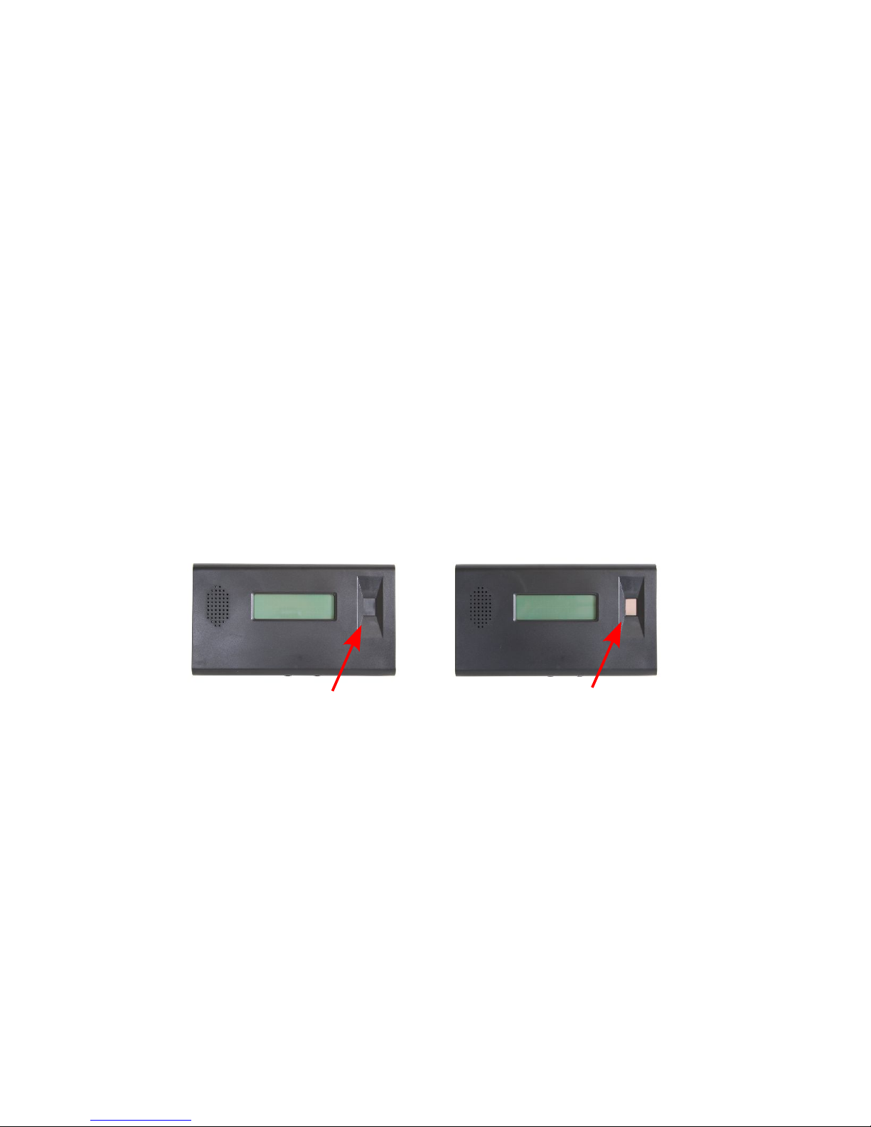
Table of Contents
IPS120T Series Overview...........................................................................................3
Prepare and Plan....................................................................................................3
Layout and Installation Considerations.................................................................4
Mounting and Connecting the TimeIPS IPS120T ......................................................5
Initial Configuration of the IPS120T..........................................................................6
Setting a Remote Master IP Address...........................................................................6
Network Troubleshooting............................................................................................7
Accessing System Menu.............................................................................................8
Additional Network Settings.......................................................................................9
IPS120T-B Biometrics Mounting..............................................................................10
IPS120T-B Biometrics Training................................................................................11
Technical Support......................................................................................................12
System Specifications...............................................................................................12
IPS120T Series Overview
The TimeIPS IPS120T is a Network Time Clock that connects via an Ethernet
network to a TimeIPS Server ("master") system. The IPS120T-B option includes a
biometric sensor for employee verification when clocking:
IPS120T - No biometric sensor IPS120T-B - Biometric sensor installed
Prepare and Plan
The TimeIPS network time clocks are designed to be connected on a LAN (Local
Area Network) or at remote locations on a WAN (Wide Area Network). For WAN, a
secure VPN (Virtual Private Network) is recommended.
We recommend a TimeIPS clock at each employee entrance to your facility and/or
in your central break-room. Each clock will require an AC power outlet and a
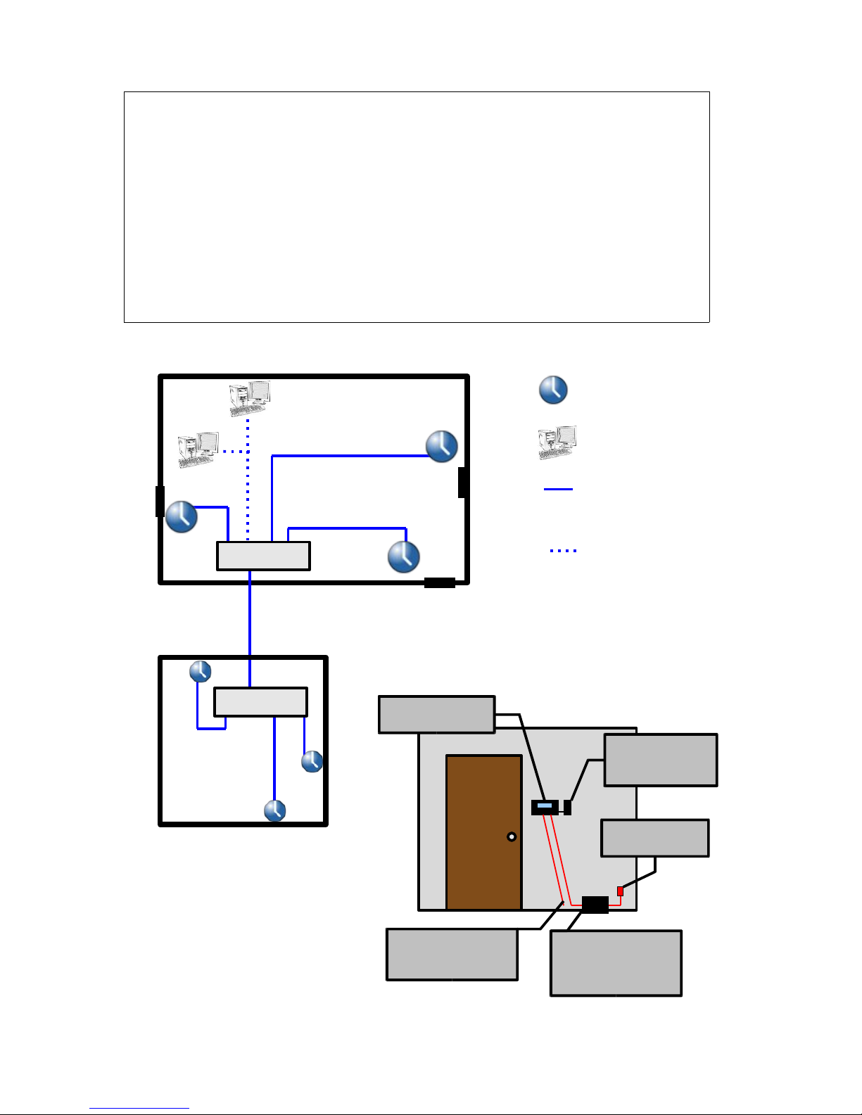
connection to your network. Please examine the diagram on the next page to assist
in planning your TimeIPS installation. Most installations will have the first clock at
the main employee entrance. Additional clocks can be added at any time to other
entrances or any location within your business.
TimeIPS http://support.timeips.com 316.264.1600 Page 3
Page 4
Layout and Installation Considerations
Page 4 http://support.timeips.com 316.264.1600 TimeIPS
IPS 120T Clock
Employee
Identification
device(s)
Power S ourc e
(Wall outlet)
Optional UPS
Power Bac kup
(not included)
Failure to mount and maintain the IPS120T unit as directed may void the warranty:
● Mount the unit in a dry, indoor location with controlled temperature and humidity. Do
NOT use the unit in any location where rapid temperature changes may cause
condensation. The rated operating temperature is between 0C and 33C (32F to 90F).
● Do not store or use the device in locations that would expose the unit to direct sunlight.
Prolonged exposure to sunlight may cause overheating and/or other damage.
● The unit will become warm during normal use. This does NOT indicate malfunction.
● Mount the device away from strong magnetic or electro-magnetic fields, such as those
produced by microwave ovens, two-way radios, or industrial equipment.
Possible Primary and Remote Facility Insta llation
Existi ng Eth ernet
10 /10 0 Netwo rk
Existi ng Eth ernet
10 /10 0 Netwo rk
Primary
Facility
Administration
and
Reporting
(Password
Protected)
Side
Door
Front
Door
Back Door
Remote
Facility
Typical Door Area Insta llation
TimeIPS Clocks
Any PC with a web
browser
Permanent network
connection
Permanent or
temporary network
connection
Network Cable
connected to
your LAN
Page 5
Mounting and Connecting the TimeIPS IPS120T
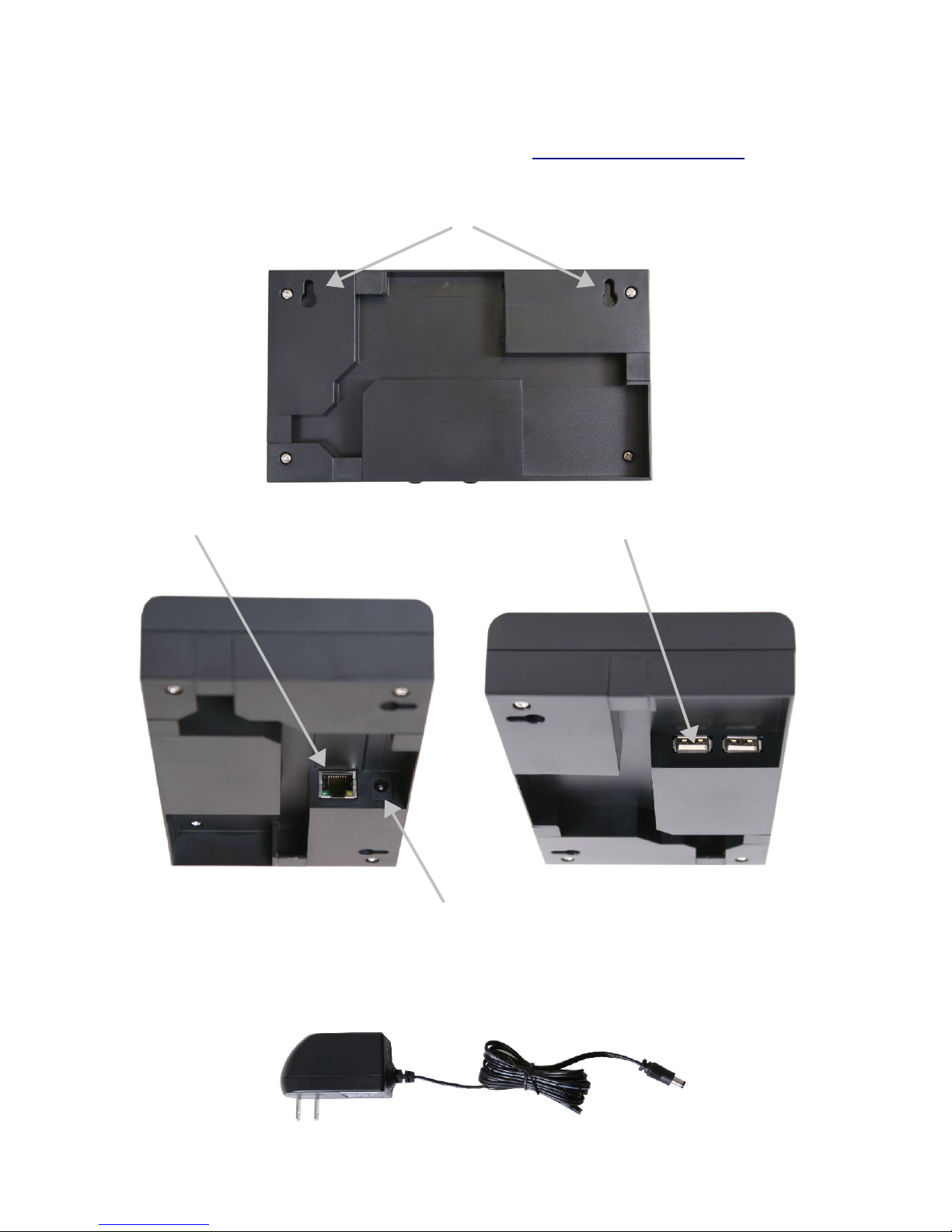
A detailed mounting guide with templates and tamper-resistant options for the
IPS120T is available in the downloads section of http://support.timeips.com. In
most cases, the IPS120T can simply be mounted with two #6 pan head screws using
the wall mounting tabs.
Connect the network. Connect employee identification device(s) to the USB ports.
Only use the supplied 5VDC 2.6A (Positive Center) power adapter (or optional
TimeIPS Power Over Ethernet adapter). Connecting any other adapter or power
supply may damage the IPS120T and will void the warranty.
TimeIPS http://support.timeips.com 316.264.1600 Page 5
Page 6
Initial Configuration of the IPS120T
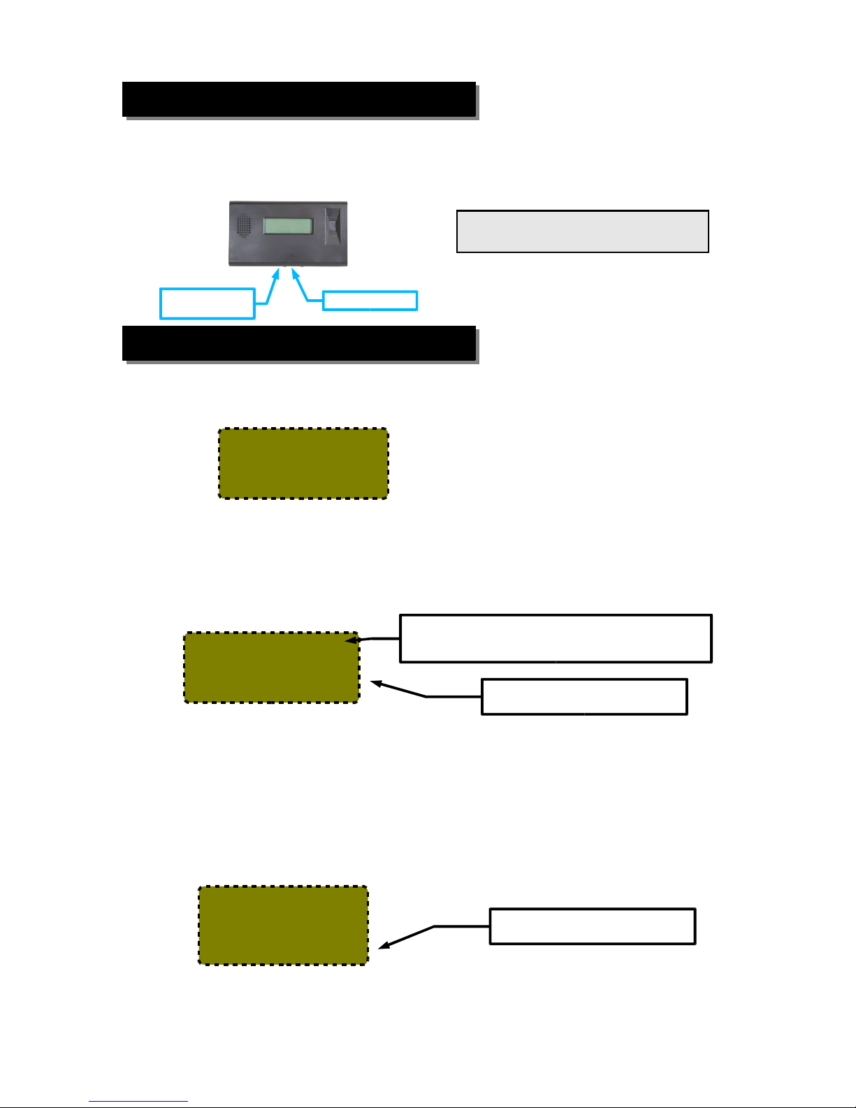
The clock will continue the start-up process for about another 30-60 seconds. When
the start-up process is complete you should see a screen similar to this:
Your new clock must connect to a master station in order to allow your employees
to clock in and out. Using your keypad (or a USB keyboard if you do not have a
keypad) select Search for Master and press Enter. The screen on your IPS120T
should flash “Starting TimeIPS” for a few seconds. You should then see a screen
that looks similar to this:
Setting a Remote Master IP Address
If your IPS120T returned to the “Clock Not Set Up” screen, it was unable to
connect to your master station. If your master station is outside of your local
network, you will need to specify the IP address of that master. Select “Configure
Network” and press Enter. Scroll down to “Set Master IP” and press Enter. You
should see a screen similar to this:
Page 6 http://support.timeips.com 316.264.1600 TimeIPS
After the employee identification device(s) and network cable are attached, poweron the clock by plugging in the power cord. In 10-15 seconds you should see
“Starting TimeIPS” on the LCD. (If not, unplug for 2-3 seconds and try again.)
Contrast
knob
Volume knob
Note: If your display does not show text,
adjust the contrast knob until text appears.
Step 2) Network Connection Verification
-Clock Not Set Up-
->Search For Master
Configure Network
Clean Shutdown
Step 1) Setting Up the IPS120T
Oct 03, 12:00:00PM
+: In -: Out
/: Check Status
or enter your ID
Oct 03, 12:00:00PM
NETWORK SETUP
Enter Master
This screen indicates that the
clock's configuration is complete.
Enter your master TimeIPS system
IP address here.
Upper case (AM/PM) indicates the clock is
communicating with your server. Lower case (am/pm)
indicates the clock is operating in offline mode.
Page 7
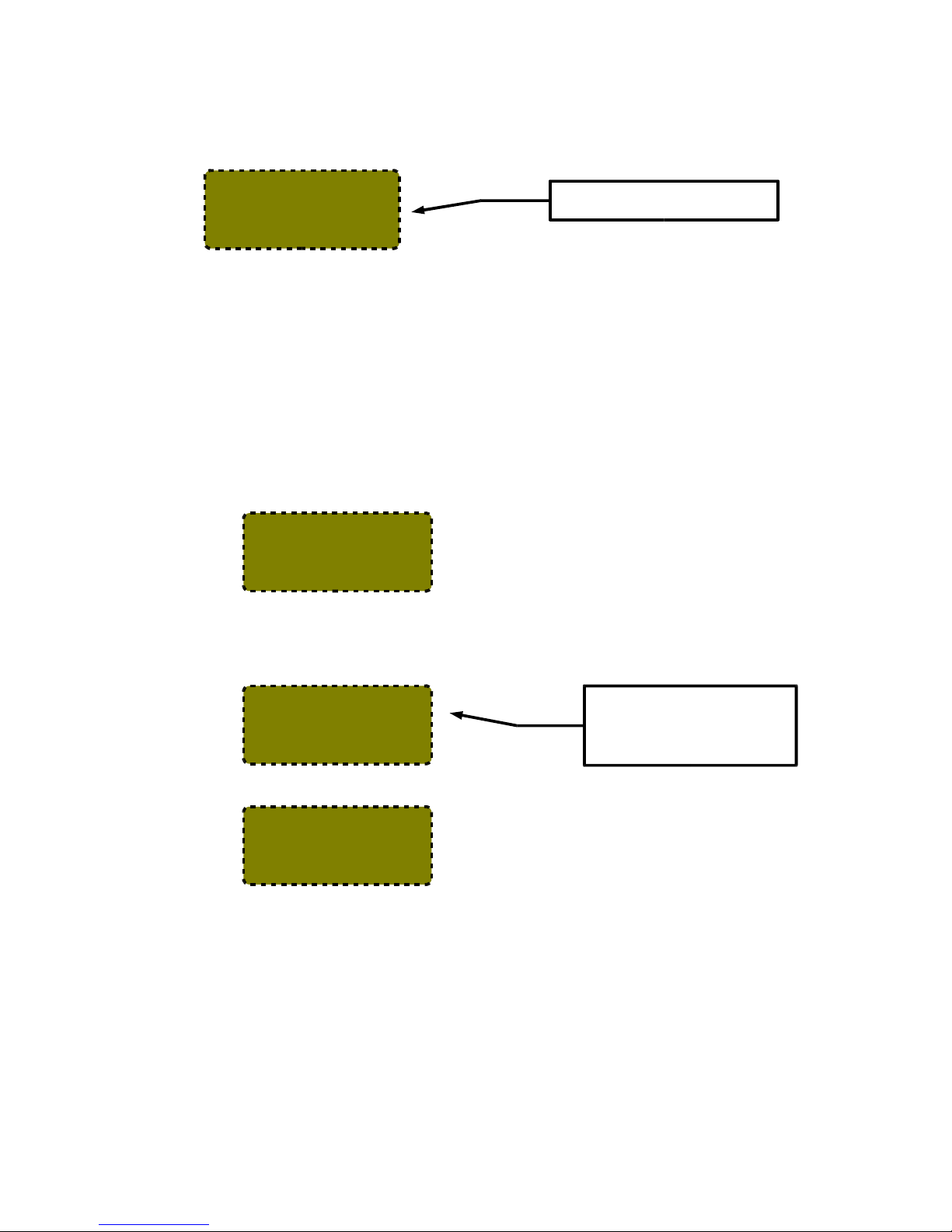
Enter the IP address of your master station and press Enter. After a few seconds you
should return to the “Configure Network” menu. TimeIPS will attempt to connect
to the supplied IP address of your master station. This may take a few moments. If
your IPS120T was successful in reaching your master station you should see a
screen similar to this:
Network Troubleshooting
In the event that your clock is still unable to reach your master you may need to use
a static IP address (if so, go to page 9), or you may be having network problems.
The first step is to verify your clock has received an IP address from your network.
1) Your clock is set to automatically obtain an IP address from your network via
DHCP by default. To see the IP address of your TimeIPS IPS120T, use the arrow
keys on your keypad to scroll down to “Configure Network” and press Enter.
TimeIPS should display a screen similar to the following:
Select “Show Network Info” and press Enter to see the IP address of your TimeIPS
clock. You should see something like this:
2) If no network connection was detected you should see the following screen:
If you see this screen, check the network cable on the back of the TimeIPS unit.
Unplug and reconnect the network cable at both ends and/or try a different network
cable. The green link light should be on. If not, your network is not working.
Once you have checked the cable and/or reconnected it, scroll down to “Revert to
DHCP” and press Enter. When you return to the “Configure Network” menu, scroll
down to “Apply Settings” and press Enter. This will cause TimeIPS to rescan your
network for an IP address. Repeat step 1 above to check the IP address TimeIPS has
received. If TimeIPS is still unsuccessful in obtaining an IP address, please contact
our Technical Support department for further assistance.
TimeIPS http://support.timeips.com 316.264.1600 Page 7
->Show Network Info
Set Master IP
Revert to DHCP
Set IP Address
Ver: 5.0.29
IP: 192.168.1.106
GW: 192.168.1.1
Mst:
The actual IP addresses shown
on your LCD display w ill be
different from this example.
Your version number may also
differ from this example.
Ver: 5.0.29
IP: 127.0.0.1
GW:
Mst:
Oct 03, 12:00:00PM
+: In -: Out
/: Check Status
or enter your ID
This message indicates that the
clock's configuration is complete.
Page 8
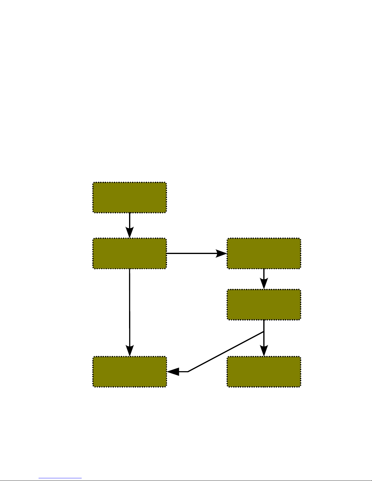
Accessing System Menu
If you need to access the menu on your clock you will need to press Enter on your
keypad. To prevent tampering, you can configure the clock to require a badge
number and PIN for access. Initially, no badge number or PIN is needed.
If a badge number and PIN are provided, you will see the User Menu. From here,
the System Menu can be accessed through the System Admin menu item. Users
with administrative access will see a full system menu while those without
administrative access will see a limited system menu.
On your master station you can set “Security and Validation Options” per clock via
the “Clock Configuration” page. These settings are independent of any employee
badge or PIN numbers. Pressing the BS key at any time will take you up one level
in the menu system.
Page 8 http://support.timeips.com 316.264.1600 TimeIPS
Full System Menu
Start Screen
Press Enter
Press Enter
(Only if clock is
not configured to
require a badge
and PIN number)
Enter your
badge
Enter your PIN
Limited System Menu
User Menu
Select System Admin
Oct 03, 12:00:00PM
+: In -: Out
/: Check Status
or enter your ID
Oct 03, 12:00:00PM
System Menu
Enter Badge Number
Oct 03, 12:00:00PM
System Menu
Enter PIN Number
Check Status
View Benefits
Request Benefits
->System Admin
->Update Settings
Play Test Sound
View System Info
Remote Service
->Update Settings
Configure Network
Play Test Sound
Use Biometrics
Page 9
Additional Network Settings
If needed, the TimeIPS IPS120T can be assigned a static IP address on your
network. You may set a static IP address using the menus, or, if it has a DHCP
address and you want to change to static, you can use the web interface provided by
the IPS120T.
(A) If your clock has a DHCP address, but you want to change it to a static address,
the first option is to use the web interface of the clock. To do this, enter the address
of the clock into a web browser of any computer on your network:
http://192.168.1.106/
Your web browser will take you to a page where you can set the IP address, Subnet
Mask, Default Gateway, Primary and Secondary DNS servers and the NTP server
for this clock. Be sure to click on “Apply Changes” to store your settings.
(B) To set a static IP address through the clock menu you must be an administrative
user. Access the menu and navigate to the Full System Menu. Scroll down to
“Configure Network” and press Enter. Then scroll to “Set IP Address” and press
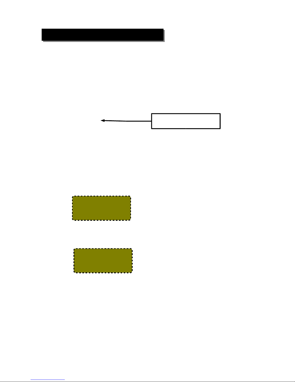
Enter. You should then see a screen similar to the following:
Specify the IP address you want this clock to have and press Enter. You will see a
screen similar to this:
In a few seconds you will return to the “Configure Network” screen. You do not
need to actually select “Apply Settings” until you have changed all of the network
settings. This usually includes the IP address, Subnet Mask, Gateway and Primary
DNS server.
TimeIPS http://support.timeips.com 316.264.1600 Page 9
Oct 03, 12:00:00PM
NETWORK SETUP
Enter IP Address
Be sure to use the current IP
address of your TimeIPS IPS120T.
Setting a Static IP Address
Select
“Apply Settings”
to apply network
changes.
Page 10
Repeat this process to set additional network parameters, such as your Subnet Mask,
Gateway, Primary DNS server and Secondary DNS server. You may also specify
your NTP server if you know its IP address. If you know your NTP server by its
name (such as ntp.yourcompany.com) you will need to use a USB keyboard or enter
this information through the web interface. Be sure to select “Apply Settings” to
save your changes.
If you have set your clock to a static IP address you can easily change it back to
DHCP. You will need to be an administrative user. Access the menu and navigate
to “Configure Network.” Scroll down to “Revert to DHCP” and press Enter.
You will need to select “Apply Settings.” In some cases, you may need to perform a
full restart or power cycle for the change to take effect.
IPS120T-B Biometrics Mounting
The IPS120T-B unit should be mounted at approximately eye-level for employees to
use the biometric option most successfully.
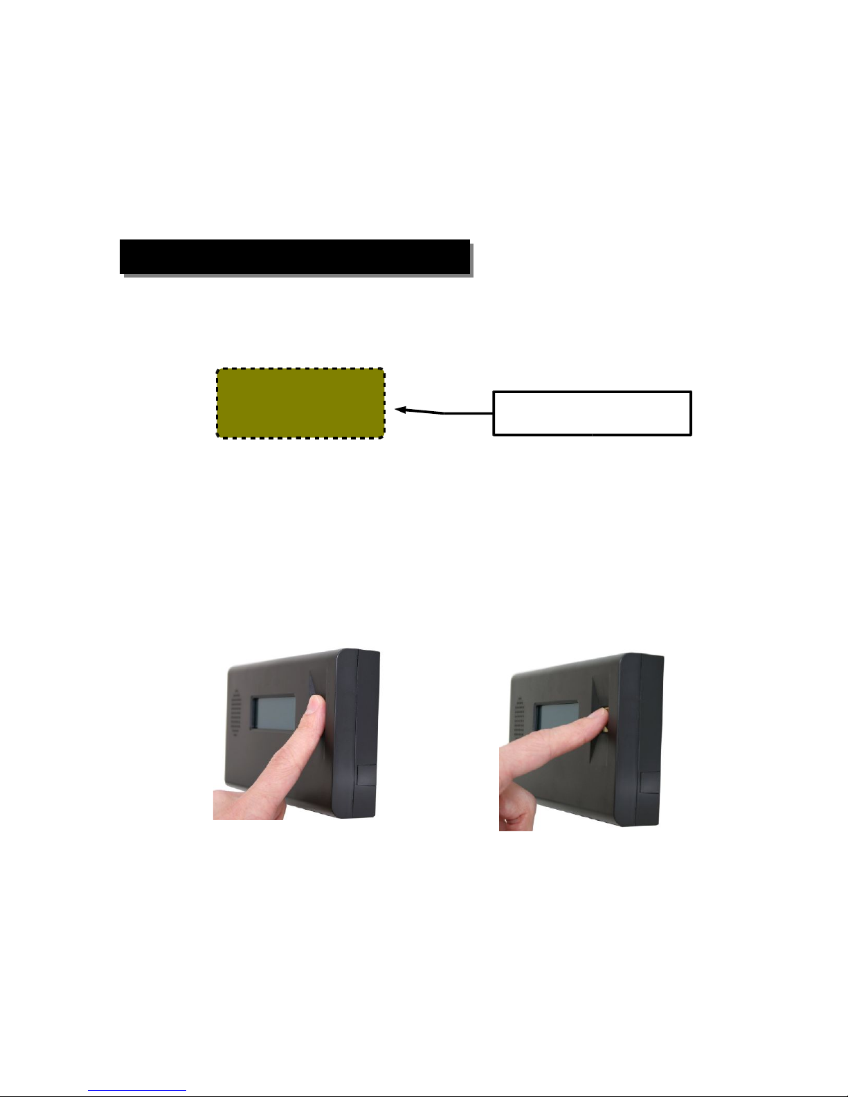
The IPS120T-B must be mounted so that fingers can be placed flat against the
sensor as shown on the left. The biometric sensor WILL NOT WORK with the tip
of the finger on the sensor as shown on the right.
Note: Keep the fingerprint sensor clean with a soft, dry cloth. Do NOT use cleaning
products on the unit as they will damage the sensor.
Page 10 http://support.timeips.com 316.264.1600 TimeIPS
Reverting to DHCP
Show Network Info
Set Master IP
->Revert to DHCP
Set IP Address
Be sure to select Apply Settings to
save your changes.
X
CORRECT
INCORRECT
Page 11

TimeIPS http://support.timeips.com 316.264.1600 Page 11
For client station:
If the client station is properly connected to your network, the following message
will appear on the display after it has found the master station on your network:
Note: If you see the message (Fig. B) above and you only have one TimeIPS station, this is your
master station and it has already been configured. It is now ready to accept clock-in/clock-out
events.
If you DO NOT see the message above on your LCD display (Fig. B), proceed to step 3
IPS120T-B Biometrics Training
Configuration in the Master:
The configuration area for biometrics is done is three places on the Master:
1) Administration → Clocking → Biometric Validation: General biometric
options and defaults for employees.
2) Administration → Employees Management→Employee Biometrics:
Employee specific options and enrollment management.
3) Administration → System Administration → Clock Configuration: Options
for biometric behavior of this specific network clock.
On the biometric options page, we suggest using a minimum of 2 enrollments and
10 progressive enrollments per employee. For even better results, use 10
enrollments on 2 fingers (5 times per finger, in different positions).
Employee Training:
Read the biometrics section of the Employee's Guide to TimeIPS (download from
support.timeips.com). This guide shows how to properly position the finger and
how to enroll in different positions for best results.
Employee Enrollment:
Enrollment will begin automatically the first time an employee clocks in or out.
The normal enrollment process requires that an employee place the same finger or
thumb against the reader a number of times to improve the reliability of matching.
Quick Enrollment:
Employees should present their finger or thumb in a slightly DIFFERENT position
for each read. This makes future authentications more reliable.
Multi-Read Enrollment:
Employees present their finger or thumb in the SAME position three times for each
of the positions above. The best read of each position is used.
Progressive Enrollment:
Additional prints are automatically added each time an employee clocks
successfully. This allows the system to improve recognition over time, but slows
the clocking process by a few seconds while all prints are evaluated and the best is
selected after each clock.
Page 12

Technical Support
Technical Support Resources:
1. Our support web site at http://support.timeips.com offers extensive
resources including documentation and our knowledge-base. Please check
our support web site first, as it provides complete answers and instructions
on almost everything. In the "Knowledge Base Search:" box, enter a few
words describing your question. For example, if you have a question on
network setup, enter "network" and browse the articles listed.
2. If you have a question not answered on our support site, you can call or
email us. A period of limited email/phone support is included with your
system. A serial number or registration number is required for this service.
Additional support can be purchased by calling TimeIPS, or by visiting our
web site at http://secure.timeips.com.
3. If you have a simple question, or need direction on how to use our support
resources, feel free to email us at [email protected]. If your question
is quick, we'll be happy to help. If it's not, we'll let you know that you
need to purchase additional support.
Support website http://support.timeips.com
Support e-mail [email protected]
Support phone number 316.264.1600
This manual is copyright 2004-2009 TimeIPS, Inc. TimeIPS and the TimeIPS logos are registered
trademarks of TimeIPS, Inc. All other trademarks are the property of their respective owners.
Thank you for reading this manual carefully. If you noticed errors, have any suggestions or found
typographical problems, we want to know! Please send an email with the version code below and your
feedback to [email protected] We appreciate your time. Version: IPS120T_1.0.4 090320
Page 12 http://support.timeips.com 316.264.1600 TimeIPS
System Specifications:
Approximate dimensions:
7.25in (185mm ) x 4in (102mm) x 1.5in
(34mm)
Approximate weight:
1lb (~.45kg) including power adapter
Power: 100-240VAC, 50-60Hz
Power consumption: 5W (typical)
Operating environment:
Dry, indoor location out of direct sunlight
32° - 90°F (0° - 33°C) non-condensing
Requirements:
TimeIPS Master Server or IPSASP service
LAN/WAN Network Connection (RJ45
Ethernet)
Biometrics (IPS120T-B):
Capacitance area sensor. Two-factor 1:1
matching for highest reliability.
Display:
4x20 LCD display with backlight
Connectivity:
2 USB ports for identification devices
such as keypads and badge readers
 Loading...