

Page 1

MOTION SENSOR
PIR LIGHT SWITCH
Cat No. ZV810
INSTALLATION & OPERATING
INSTRUCTIONS
Page 2
ZV810 Motion Sensor PIR
Light Switch
Please read the instructions before using the
product and retain for future use.
Content
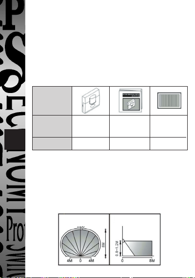
Pattern
Item Light Instructions Silver
1
Quantity 1 1 1
Switch Label
Coverage
The ZV810 can be installed at various heights
from 0.8M to 1.2M to detect a zone up to 8M in
range over a 180º angle. ( See Fig .1 )
Top View SideView
Fig. 1
Page 3

Installation and Wiring
This product must be wired in accordance
with the IEE Wiring Regulations. If you have
any doubt about your ability to install this
product consult a competent electrician.
Switch off the power supply before
installation and wiring.
A. Select a location
• For indoor use only ie: hallways, diningroom, basement, utility rooms and garages,
etc. To replace existing one way or two way
light switches.
• Since the ZV810 is sensitive to temperature
2 3
changes. Avoid mounting directly above heat
sources or exposed to direct sunlight.
• Avoid mounting the motion sensor switch where
it can come into contact with water or rain.
• For best results mount the sensor switch to
detect objects moving across it. (See Fig.2)
More Sensitive Less Sensitive
Fig. 2
Page 4

To avoid nuisance triggering
Your sensor switch may be activated by large
animals, lights, reflective surfaces, heat sources
or movements of objects.
The following guidelines will help you to avoid
nuisance triggering:
• Do not aim the sensor towards any light sources.
• Avoid mounting the sensor near heat sources,
such as heating vents, air conditioners, dryer
vents or lights.
• Avoid directing the sensor toward areas or
whose surfaces are highly reflective or are
subject to rapid temperature change, such as
pools.
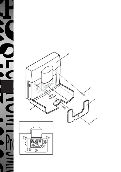
B. Installation procedure
1. Ensure the power supply is switched off.
2. Open the front cover, to reveal the fixing
screws (See Fig.3)
3. Loosen the screw and take apart the inner
frame.
4. Refer to wiring diagrams, for wiring
instructions.
5. Fix the motion sensor wall switch to the wall
box with screws supplied.
Page 5
6. Adjust the "TIME ", "METER" and " LUX "
knobs for "Walk Test " over the desired
detection zone. (See Fig.4)
7. Screw the inner frame in place and replace
the lifting-front cover.
Front
Cover
Fig. 4
Sensor
Slide
Switch
Fig. 3
Mounting
Screw
Inner
Frame
Screw
Page 6

C. Wiring Diagrams
1. To replace a one way switch.
(See Fig.5 )
• Wire dimension:
Min. 0.5mm
Max. 2.0mm
2
2
2. To replace a 2 way switch in a two way
circuit. (such as stairs), (See Fig. 6)
• To replace a 2 way
switch please refer
5
Fig. 6
to Fig. 7 for wire
connection and add
a link to the remote
switch.
• When the Remote
Switch is actuated,
lights will remain on
for the pre-set period.
Fig. 7
Remote
Switch
ZV810
3. To replace both 2
way switches in a
two way circuit.
Fig. 8
ZV810
ZV810
(See Fig. 8)
Fig. 5
Page 7

Walk Test and Adjustment
A. Walk Test
1. After the main part of the motion sensor
switch has been fitted to the wall box turn the
power on to warm up sensor for at least
3 minutes to stabilize the sensor for normal
operation before carrying out the "Walk Test".
2. Switch the sensor switch to the middle
position for "AUTO" function. (See Fig. 11)
3. Start from outside the pattern and walk
across it until the lights come on. (See Fig. 9)
4. Adjust the sensor "METER" knob as
necessary to improve coverage until it meets
64
users preference. (See Fig.11)
Walk Test
Start Finish
Fig. 9
Page 8

5. To reduce the detection area, user can put
on the silver label which is supplied with this
instruction manual to cover the lens. (See Fig.10 )
B. Adjustment the
"TIME", "LUX", and
"METER" knobs.
(See Fig. 11)
1. Adjust the "TIME"
control to set the ON
time from about 6
seconds to the
maximum 12 minutes.
This period starts after
body movement within
the detection area is
sensed.
2. Adjust the "LUX"
to set the light level
required for operation
to start at the required
light level.
3. Adjust the "METER"
to set the detection
distance up to about 8M.
7
Fig. 10
Fig. 11
Silver Label
Page 9

Operation
A. Functions of Slide Manual Switch
After fitting the unit use the slide switch to set
the "ON", "AUTO" or "OFF" functions. (See Fig. 11)
1.ON - lights “ON” manually.
Note: Set the switch in "OFF" position when
replacing lights or fuses.
2.OFF - lights “OFF” manually.
3.AUTO - lights “ON” or “OFF” automatically
according to the “METER”, “TIME” and
“LUX”, control settings.
B. Operations in Different Wiring Conditions
8 9
1. When one or two sensor switches are used in a
circuit. Sensor switch A should be set to the
"AUTO" position.
2. When the sensor switch is in a two way circuit
(See Fig. 7), the remote switch acts as a momentary
switch. It can only trigger the sensor switch to
turn the lights when the slide switch is set to the
"AUTO" position. Thus, the two-way circuit will
be controlled by the sensor switch.
3. When two sensor switches are used in a two
way circuit (See Fig. 8) the operation will be as
follows:-
Page 10

A Sensor B Sensor Switch Light
Slide Switch Slide Switch Controlled
Position Position Status
ON ON ON
OFF ON ON
OFF OFF OFF
AUTO AUTO AUTO
AUTO ON ON
AUTO OFF AUTO
Note: Do not use with fluorescent and PL
lamps that have conventional ballast (iron
ballast). This will damage the starter and cause
the ZV810 to retrigger.
Troubleshooting
Each sensor switch has undergone rigorous
testing and quality control, malfunctions are
mostly due to incorrect installation or exposure
to heat souces.
Lights Do Not Turn On
1. Turn off power for at least 5 seconds, then on
again.
Page 11

2. Check that lights and fittings work properly.
Compare wiring to the wiring diagram. Check
that power is on.
3. Check that the slide switch is not in the
"OFF " position.
4. Check the fuse.
Lights Come On And Off Quickly
1. Heat from lights will cause unsteady sensor
performance.
2. Make sure lights are not reflecting back into
the sensor. Check for white or reflective surfaces
in the protection pattern. If so aim sensor and
lights in a different direction.
3. Note that the sensor is more sensitive in
winter since infrared energy is easier for the
sensor to detect in cold temperature. Turn
"METER" knob closer to " - ".
Lights Do Not Turn Off
1. Check that the Time control knob is set to
minimum.
2. Check that the slide switch is in the "ON"
position.
3. Keep out of the detection area to avoid
activating.
Page 12

4. Make sure the unit is not mounted on an
unstable object which is warm. Make sure the
unit is firmly mounted.
5. Make sure the unit is not aimed at something
that would cause a temperature change such as
air conditioners or heating vents.
6. Turn power off for more than 5 seconds, then
turn on again to resume automatic operation.
7. Make sure line voltage is stable.
Note: Keep the lens area clean and free of
obstructions. Do not attempt to open or repair
the unit.
11
Do not use with dimmer or any other switch
containing electronic circuit.
This is the silver label which can be used to
cover the lens as (Fig.10) shown.
Page 13

Specifications
Supply Voltage: 230VAC 50Hz.
Permissible
Loads: 40-500W for incandescent light.
40-150W for low voltage
halogen light.
18-150W for fluorescent light
with electronic ballast.
15-150W for electronic PL lamp
(Philips, Osram only).
Light ON Time: Adjustable from about 6 seconds
1210
Lux: Fully adjustable light level
Detection Range: Adjustable up to 8 meters( 20ºC ).
Detection Angle: Up to 180º ( 20ºC ).
Fuse Protection: 3.15A, 5 x 20mm changeable
Manual Switch: OFF /AUTO / ON
Operating
Temperature: -10ºC ~ +45 ºC
Environmental
Protection: IP30.
to 12 minutes.
sensitivity for sensor to be
activated at the desired
brightness in daytime.
Page 14

3 Year Guarantee
In the unlikely event of this product becoming faulty
due to defective material or manufacture within 3
years of the date of purchase, please return it to your
supplier in the first year with proof of purchase and
For the second and third years or any difficulty in the
it will be replaced free of charge.
first year telephone the helpline on 020 8450 0515.
HELPLINE
020-8450-0515
For a product brochure please contact:
Timeguard Ltd.
Victory Park, 400 Edgware Road,
London NW2 6ND
020-8452-1112
or email csc@timeguard.com
 Loading...