

Page 1
7 Day Digital Lightswitch
with Optional Dusk Start
Cat No. ZV700
Installation & Operating Instructions
Page 2
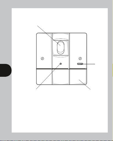
ZV700 – Lower Flap Closed
Rocker switch – used in
manual operation
Supply
ON LED
1 2
Photocell window
Lower flap hinges
open – see page 2
1. General
The ZV700 combines the function of a manual lightswitch with
automatic timed control of lighting on a weekly basis available at the
slide of a switch. There is a further option of starting an automatic lighting
period at dusk but ending it in the usual way with a timed “OFF”.
Page 3
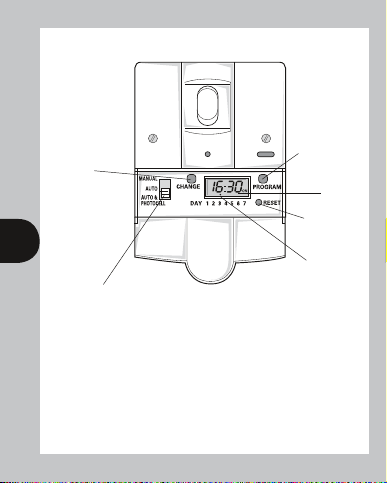
ZV700 – Lower Flap Open
Override button
– also used in
conjunction with
the programme
button to set the
clock and ON/
OFF times, days
and random
facility.
Guarded
tamper
resistant button
used to
programme
clock and
times/days for
ON periods
24 hour
display
Tamperproof
Reset button
2 3
Day marker
Three position slide switch giving MANUAL operation, AUTO
operation with timed ONs and OFFs or AUTO and
PHOTOCELL operation giving dusk start and timed OFF with
additional timed ONs and OFFs if required
The unit is easily programmed using the two buttons and the digital display.
Either automatic mode is selectable using the three position slide switch and in
the third position,manual mode, the lamp is turned ON and OFF as normal
using the rocker switch.
The unit has two enhanced features, the first is battery back-up of clock time and
programme memory and the second is the ability to switch low energy, fluorescent
and low voltage lighting.
Page 4
Important Installation Instructions
IF IN DOUBT CONSULT AN
ELECTRICIAN.
Switch off mains electricity
Remove the existing light switch and transfer
the wires to the security switch according to
the following instructions.
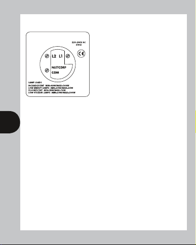
If the switch is an ON/OFF two wire type,
those wires should be inserted into the
any earthing wire connected to the wallbox terminal. If the switch is a 2-WAY
switch, used in conjunction with a second light switch, it will have 3 wires.
In this case the wire originally connected to the COM terminal must be inserted
into the COM terminal, the remaining two wires connect to terminals L1 and L2
3 4
in either position.
If two wires are connected to any one terminal on the original switch, these should
be kept together and inserted into the corresponding single terminal on the Digital
Security Switch. Ensure that the terminal screws are tight before refitting the unit
to the wall box and turning on the mains electricity. Lower the hinged cover, move
the slide switch to the MANUAL position and check that the rocker switch operates
the lamp normally. The unit terminals are suitable for 1mm
conductors and stranded equivalents.
Note: The unit will replace any conventional single or
two way switch.
It cannot be used as an intermediate switch and cannot be used
in conjunction with a lamp dimmer in 2 way switching.
terminals marked L1 and COM. Do not disturb
2
and 1.5mm2 solid
Page 5

2. Commissioning
After having installed the unit in accordance with the installation and wiring instructions on
the back of the blister card, move the slide switch to the AUTO & PHOTOCELL position
(this is important because the unit always powers up in this mode regardless
of switch position), and switch ON the supply to the unit. The LED should now light up,
if it does not then either the supply is not present or all the lamp(s) under control are not
present or faulty. If the display is not already showing clearly allow the factory fitted
rechargeable battery to charge up by moving the slide switch to MANUAL and turning the
rocker switch to the OFF position (lamp OFF). Four hours is the minimum time which should
be allowed for charging after which the unit will be ready for commissioning. The unit can
now be checked for correct operation by moving the slide switch to the AUTO position and
then pressing the <Reset> button with a pen or matchstick until the display disappears and
then clears to show 0:00 (system reset). If the rocker switch is turned to the ON position
and the <Change> button is pressed the ON symbol will be shown on the display (flashing
to indicate an override) and the lamp(s) will be turned ON. The unit is now ready for
4 5
programming (see Programming Instructions).
3. Operation in MANUAL Mode
(as an ordinary lightswitch)
Move the slide switch to the MANUAL position. The lamp can now be switched ON and
OFF using the rocker switch and AUTOMATIC operations are inhibited. Switching the
rocker switch OFF, when the lamp(s) are ON in either MANUAL, AUTO or
AUTO & PHOTOCELL mode, can produce visible arcing. This is quite normal
and there is no cause for alarm.
4. Operation in AUTO Mode
Move the slide switch to the AUTO position and turn the rocker switch ON.
The unit will now execute any switching programmes in its memory (see Programming
Instructions). In this mode the rocker switch can be used manually to turn the lamp OFF once
a programmed ON period has started, but not to turn it ON during a programmed OFF period.
Page 6

5. Operation in AUTO & PHOTOCELL Mode
Move the slide switch to the AUTO & PHOTOCELL position and turn the rocker switch ON. In
this mode the unit will turn ON at dusk and OFF at a time programmed by the user. To do this it
needs an ON time prior to dusk to be programmed by the user along with the above OFF time
(see Programming Instructions). A safe ON time to cover the whole year anywhere in the U.K. is
1400 hours. A additional ON period can be programmed for the early morning if required. This
will only operate if the ON time occurs in darkness and will last until the programmed OFF time.
In this mode the rocker switch can be used manually to turn the lamp OFF once a programmed
ON period has started, but not to turn it ON during a programmed OFF period.
ZV700 – Programming Instructions
5 6
Override button (also
used in conjunction with
programme button to
set the clock and ON/
OFF times/days)
6 Battery
This product has a factory fitted rechargeable battery. If the unit is left with its mains power
switched off for more than 1 month the display may go blank. In this case switch mains on,
wait four hours, and apply reset – see 9 before programming.
7. Programming Overview
This is a seven day (weekly) timeswitch which has six programmes, each of which can be block
programmed to work on all of the five weekdays, both weekend days, or all 7 days (24 hour
operation). Programmes can also be designated to operate on individual days.
Day
marker
24 hour
Guarded tamper resistant
display
programme button used to
select the clock time and the 6
“ON/OFF” times/days and to
review them once set
Page 7

Only two setting buttons are required, <Change> and <Program>. The <Program>
button is guarded to minimise inadvertent programme change. In normal operating
mode the <Change> button is used to switch ON or OFF, overriding the timeswitch
until the next programmed OFF or ON time. During programming the <Change>
button is used to set the hours, minutes and days. The <Program> button is used to
select the clock time and day or the 6 programmed ON/OFF times and days and to
review them once they have been set. Each time the <Program> button is pressed
in programme mode the display will flash either the days, hours or minutes in turn,
starting with the clock time and day then the first ON time and day(s), first OFF
time, second ON time and day(s) etc. Wherever the days, hours or minutes are
flashing they may be set using the <Change> button. Once set the <Program>
button is pressed again to proceed to the next stage. Programming can be carried
out with the slide switch in any position and with the lamp ON or OFF.
8. Normal Operating Mode
In normal operation the unit will display the correct day
and its time with the colon flashing. The output status
will be shown by either ON or OFF on the display.
6
9. To Reset Before Programming
(To alter clock time or modify programmes –
see section 12)
To clear programmes from memory and reset the unit
press the reset button with a pen or matchstick until
the display goes blank. Release the button and the
display will fill with its complete range of characters and
then clear to show clock and day 1 symbol flashing.
This procedure is essential with a new unit and is
recommended if major reprogramming is required subsequently.
You are now in the clock setting mode at the beginning
of the programme sequence
Page 8
Programming sequence
Setting clock
Programme 1 ON
Programme 1 OFF
Programme 2 ON
Programme 2 OFF
Programme 3 ON
Programme 3 OFF
Note: Pauses between button presses greater than 1 minute during
programming will result in automatic return to the operating mode.
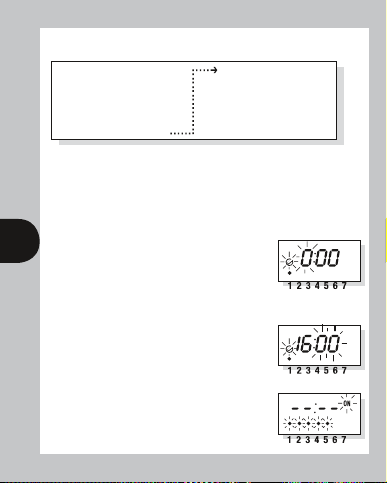
10. Setting Clock (after reset)
i Day Setting – Press <Change> button to advance to the day required.
Day 1 = Monday and Day 7 = Sunday.
ii Hour Setting – Press the <Program> button briefly
to select the hours – display shows clock symbol and
7 8
the hours digits flashing.
Press the <Change> button to advance the hour
setting. For rapid hours selection press and hold down
<Change> button. (Note: Monday shown as example
of day set.)
iii Minute Setting – Press the <Program> button briefly
to select the minutes – display shows clock symbol and
minute digits flashing. Press the <Change> button
to advance the minutes setting. For rapid minute
selection press and hold down <Change> button.
(Note: 16 hours shown as example of hours set)
iv Press <Program> button briefly – clock is now
set and display shows ready for the first ON
programme time.
Programme 4 ON
Programme 4 OFF
Programme 5 ON
Programme 5 OFF
Programme 6 ON
Programme 6 OFF
Operation Mode
Page 9

11 To Set Programme ON/OFF Times
(after clock setting)
It must be remembered that the unit has a total of six programmes.
i The user is now able to set the day(s) that the first programme will operate on.
The alternatives are:
1 2 3 4 5 6 7
● ● ● ● ●
Initially dots 1 to 5 flash indicating that if this option were selected,
8 9
ii Once the day option has been selected press <Program>
iii Press <Program> button briefly to select minutes –
iv Press <Program> button briefly – the first ON time
v Now set the hours and minutes as before.
= 5 days (Weekdays) Mo Tu We Th Fr
● ●
● ● ● ● ● ● ●
●
= Individual days starting with Mo through to Su
the programme times about to be entered would operate over the
five weekdays. If another option is required, the <change> button
should be pressed until the correct day(s) flash.
button briefly to select hour time – display shows hour
digits and ON flashing. Press <Change> button to
advance hour setting. (Note: 2 days (Sat & Sun)
shown as examples of days set.)
display shows minute digits and ON flashing. Press
<Change> button to advance minute setting.
(Note: 16 hours shown as example of hours set).
is now set and display shows ready for the first OFF
programme time.
The day(s) selected remains the same.
= 2 days (Weekend) Sa Su
= 7 days (Everyday) Mo Tu We Th Fr Sa Su
Page 10

vi Repeat steps i to v to set the remainder of the 5 programme ON/OFF times and
day(s) as required. Note: Any unused ON/OFF programmes must be left blank and
should be skipped by pressing the <Programme> button until the display shows
normal operating mode. Do not programme ‘0’s into unused programmes.
IMPORTANT After setting a clock time which falls within a programmed ON
period, the unit will not switch ON. Press the <Change> button to switch the unit
ON. After this the unit will operate normally to the programmes set.
12 Programme Review
To fast review the set programmes or for quick exit to normal operating mode –
press and hold down the <Program> button.
Normal review can be carried out by pressing the <Program> button briefly which
reviews the clock time and day with the whole display flashing. Further brief
pressing of this button reviews the programme ON and OFF times and day(s) in
sequence again with the whole display flashing.
13 Making Changes to Clock Time and
Programmes (Initiating Programme Mode)
9 10
This is required when making changes to the clock time/day or programme times/
days and can be initiated any time during the normal operating mode. Press the
<Program> button briefly and the clock symbol, day flag, hrs and minutes symbols
on the display will flash – this is programme review mode. Further brief pressing of
the <Program> button will display the ON and OFF programmes in sequence.
Having reached the clock time/day or programme time/day(s) requiring change,
press the <Change> button briefly to initiate programme mode and then follow
steps 10 and 11 as required. Having completed the change press and hold down
the <Program> button until normal operating mode is reached and then release.
14 Cancelling Programmes
Any ON/OFF programme can be cancelled by clearing its ON and OFF time.
Follow step 13 and when into the ON and OFF programme to be cancelled press
the <Change> button briefly and the day dot(s) will flash, press the <Program>
button briefly to select the hours and press the <Change> button until the hour
digits show -- --: then press the <Program> button briefly to clear the programme
time. The display will show the hour and minute dashes and ON or OFF flashing.
Page 11

15 Programming Across Midnight
This can be achieved by programming the required ON time in the initial day and the
required OFF time in the subsequent day. The unused times in these two programmes
can either be left blank (--:- -) or used for an OFF time during the initial day and an
ON time during the subsequent day.
16 Self Cancelling Override
To change the output status from ON to OFF or vice versa press the <Change> button.
The output status will change and indicate override is in operation by flashing either the
ON or OFF symbol on the display. The override will end at the next programmed change,
or sooner, if the <Change> button is pressed again.
17 Random Operation
By pressing the <Change> for around three seconds whilst in normal operating mode a small
R appears on the display. The unit will now switch ON and OFF in a random fashion during
programmed ON periods in both AUTO and AUTO & PHOTOCELL modes. Both the ON and the OFF
periods will vary in a random way between 10 and 31 minutes. Normal switching can be restored
by pressing the <Change> button for around three seconds until the R symbol reappears.
10
Specifications
i Conforms to Directives: 73/23/EEC & 89/336/EEC.
ii Permissible Loads: Filament 40 – 300W
Low energy 20 – 150W (electronic & iron ballast)
Fluorescent 18 – 76W
Low voltage 20 – 200W
iii Battery Back-up: 1000 hours by factory fitted rechargeable battery.
iv Operating Ambient
Temperature Range: -10°C to 40°C.
v Operating Voltage: 220 – 240V AC.
vi Dusk Start: 1-5 Lux
vii Terminations: Suitable for 1mm
and stranded equivalents.
viii Control Type: 1Y
Not suitable for discharge lighting (e.g. SON and Metal Halide) and
LED lights. The unit will fit in a 16mm deep box.
2
and 1.5mm2 solid conductors
Page 12

In the unlikely event of this product becoming faulty, due to defective material
or manufacture, within 3 years of the date of purchase, please return it to
your supplier with proof of purchase and it will be replaced free of charge.
Should you encounter any difficulty please contact
For assistance with the product please contact:
3 Year Guarantee
our helpline on 0845 3554504
HELPLINE
020 8450 0515
or email helpline@timeguard.com
For a product brochure please contact:
Timeguard Limited.
Victory Park, 400 Edgware Road,
London NW2 6ND
Sales Office: 020 8452 1112
or email csc@timeguard.com
67.058.500 (issue 2).
Zerofour – October 2013
 Loading...