

Timeguard TRTWIFI Installation & Operating Instructions Manual
Installation & Operating Instructions
Wi-Fi Controlled Thermostat
Model: TRT WIFI

1
1. General Information
These instructions should be read carefully and retained for further reference
and maintenance.
Note: Timeguard reserve the right to alter these instructions, and the
Programastat+ heating app, at any time. Up to date instructions
will always be available for download at www.Timeguard.com.
2. Safety
• Before installation or maintenance, ensure the mains supply to the
thermostat is switched off and the circuit supply fuses are removed
or the circuit breaker turned off.
• It is recommended that a qualified electrician is consulted or used for the
installation of this thermostat and install in accordance with the current
IEE wiring and Building Regulations.
• Check that the total load on the circuit including when this thermostat is
fitted does not exceed the rating of the circuit cable, fuse or circuit breaker.
• To clean use a clean dry cloth only. Do not use and liquid cleaners.
3. Technical Specifications
Power Box
• Mains Supply: 220-240V AC 50Hz
• This power box is of Class II Construction and must not be earthed
• Switching Rating: 6(2)A
• Switch Type: Single Pole Single Throw (SPST)
• Installation Type: Wall Mount
• Power Consumption: 1.2W
• IP Rating: Intended for indoor use only
• Light Indicators: Red LED (Power), Green LED (Output),
Orange LED (Wi-Fi Connection)
• CE Compliant
• Dimensions (HxWxD): 101mm x 107mm x 35.5mm
Dimensions include pre-fitted cable
glands and mounting holes
2
3
Thermostat
• This thermostat is of Class II Construction and must not be earthed
• Connection: 2 wire
• Installation Type: Using either the surface mount box
supplied or a BS flush mount wall box
(min 35mm depth)
• Wi-Fi Protocol: 802.11b/g/n
• Network Protocol: IPv4 TCP
• Frequency Range: 2.412 – 2.484 GHz
• 5 Operating Modes: Permanent ON or OFF, Auto Timed,
Frost and Holiday
• Programmes: 6 timed periods per day, with weekly repeats
• Back Light: Yes
• Operating Temperature Range: 0°C to +40°C
• Set Temperature Range: Minimum +5°C to maximum +35°C
• Temperature Adjustment: 0.5°C steps
• Swing 0.5 or 1.0 C
• CE Compliant
• Dimensions (HxWxD): 90mm x 90mm x 46mm
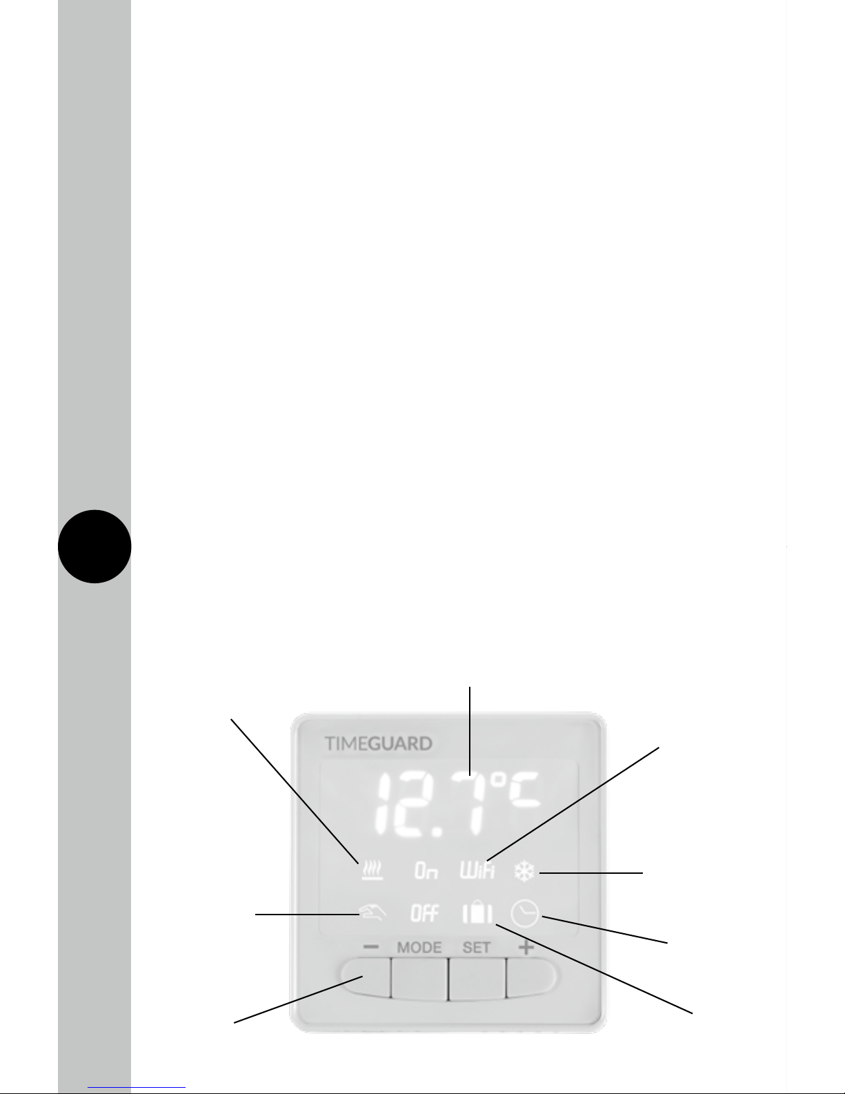
TRTWIFI Thermostat – Front View
The heating
symbol will show
when heat is
demanded
The override
symbol will
show when
temperature has
been manually
changed
+/- setting
buttons
The Wi-Fi icon
will show when
the device is
connected to
the internet
The frost symbol
will show when
frost protection
mode is active
Holiday
mode icon
Auto mode
icon
5°C to 35°C set
temperature range
3
4
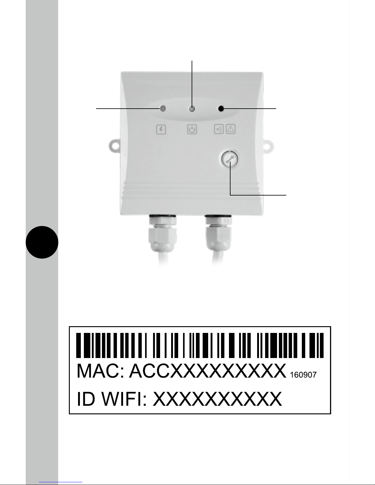
TRTWIFI Power Box – Front View
Red LED:
illuminates
when power is
supplied from
the mains
Orange LED: flashes
twice regularly when
connected to the
internet and pulses
when in pairing
mode. The orange
LED will flash quickly
when there is a
communication issue
Manual Output
Button: functions
only when there
is no internet
connection as an
ON/OFF button
Green LED: illuminates when
output is switched ON
TRTWIFI MAC address and ID Wi-Fi number label
Important: Do not remove this label from the side of the product.

4
5
4. Contents
• 1x TRTWIFI Thermostat
• 1x TRTWIFI Power Box
• 1x Instruction Manual
• Mounting Kit
Note: All instructions are to be left with the customer
after installation
5. Installation
5.1 Ensure the mains supply is switched off and the circuit supply fuses
are removed or the circuit breaker turned off.
5.2 Disconnect the mains supply from the wiring centre.
5.3 Mount the power box next to the wiring centre (where fitted),
or the boiler.
5.4 Use the power box as a template to mark the position of the mounting
screws. Drill the mounting hole taking care to avoid any joists, electrical
cables or water/gas pipes that may be hidden beneath the surface.
5.5 Insert the rawl plugs into the holes that have been drilled and align the
power box with the mounting holes. Then insert the screws and tighten
until a firm hold of the power box is ensured.
5.6 Connect the live (brown) and neutral (blue) wires on the power box
to a 230V AC supply from the wiring centre, making sure the polarities
match up accordingly with the wiring centre. Refer to the connection
diagram (section 6) for reference.
5.7 Remove the connections from the existing thermostat from the wiring
centre. If there is a neutral connection (blue) this is no longer required
for the installation and must be disconnected. Refer to the connection
diagram (section 6) for reference.
5.8 Connect the existing thermostat connections in the wiring centre to the
two black wires from the power box flex marked boiler. These are volt
free connections, and are not polarity sensitive. Refer to the connection
diagram (section 6) for reference.
5.9 Connect the previously removed wires that go from the wiring centre
to the thermostat to the white wires from the power box, marked
thermostat. The wires are not polarity sensitive. Remove the existing
thermostat if fitted. Refer to the connection diagram (section 6)
for reference.
5
6
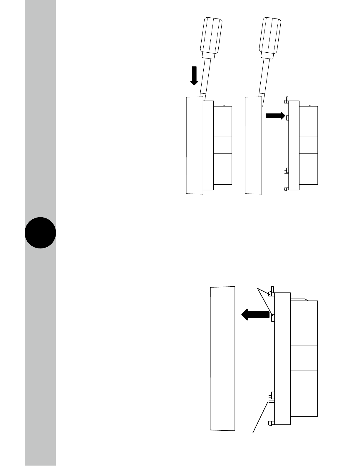
Press tab
down
Remove the
front plate
5.10 Remove the front plate of
the TRTWIFI using a screw
driver to press down the
tab on the top
of the device.
5.11 If required, use the
surface mount box
supplied, as a template
to mark the position of
the mounting screws.
Drill the mounting holes
taking care to avoid any
joists, electrical cables
or water/gas pipes that
may be hidden beneath
the surface.
5.12 Insert the rawl plugs into the holes that have been drilled.
5.13 Connect the two white coloured wires from the flex of the power box
to the TRTWIFI. The wires are not polarity sensitive. If there are 3 wires,
then omit the neutral (blue) wire.
5.14 Re-fit the front of the TRTWIFI by hooking the lower edge over the tab,
and pressing the top home until it clicks, taking care not to bend
the 8 connecting pins.
5.15 Reconnect the mains supply
to the wiring centre.
Clips
Connecting
pins
 Loading...