

Page 1

Analogue Economy Seven
Programmer
Model: TRTM7N – White
Installation & Operating Instructions
Page 2

1. General Information
These instructions should be read carefully and retained for further reference
and maintenance.
2. Safety
• Before installation or maintenance, ensure the mains supply to the time
switch is switched off and the circuit supply fuses are removed or the
circuit breaker turned off.
• It is recommended that a qualified electrician is consulted or used
for the installation of this time switch and install in accordance
with the current IEE wiring and Building Regulations.
• Check that the total load on the circuit including when this
time switch is fitted does not exceed the rating of the circuit cable,
fuse or circuit breaker.
3. Technical Specifications
• 230V AC 50 Hz
• This time switch is of Class l Construction and must be earthed
• Switch Rating: 13A Resistive (3kW) Immersion Heaters
1
• Switch Type: Micro-disconnection ON control.
• Programme: 24 hour segment dial timer
• Boost Times: 15, 30, 60, 120 minutes
• Economy Output Light: Blue LED
• Quartz Reserve: 150 hour battery life
• Tamper proof transparent cover for timer
• IP30 Rated suitable for restricted internal applications
• CE Compliant
• Dimensions (H x W x D): 111.5 x 170 x 60mm
Disconnection to immersion heater(s)
via double pole rocker switch
with 15 minute switching intervals
Page 3
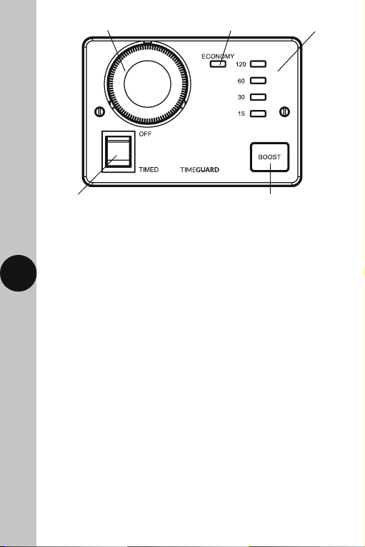
Mechanical timer Economy light Boost period indication
OFF/Timed switch
Boost button (illuminated in use)
4. Installation
Suitable for use with single, dual, or twin element immersion heaters.
4.1 Ensure the mains supply is switched off and the circuit supply fuses
2
are removed or the circuit breaker turned off.
4.2 Remove the 2 fixing screws holding the front panel to the back box.
4.3 Decide which mounting holes you would like to use and select a suitable
cable entry point by drilling into the back box ensuring not damage or
infringe on any of the internal components.
4.4 Mark the position of the mounting holes on the wall using the back
box as a template. Drill out the mounting holes taking care to avoid any
joists, electrical cables or water/gas pipes that may be hidden beneath
the surface. Insert the rawl plugs into the holes.
4.5 Pass the 230V 50Hz mains supply and load cables through the cable
entry point(s) on the back box.
4.6 Fix the back box to the wall using the correct mounting screws for the
rawl plugs installed.
4.7 Use the cable clamp in the back box to secure the cables.
4.8 Terminate the cables into the terminal block ensuring correct polarity
is observed and that all bare conductors are sleeved (See section 5.
Connection Diagram).
4.9 Ensure all terminals are secured and screw the front panel of the unit
to the back box using the 2 fixing screws previously removed.
Page 4

230V~50Hz
MAINS SUPPL
L
E
N
Neutral
Load
Earth
5. Connection Diagram
Connect the cables to the terminal block which are marked as follows;
• 230V 50Hz mains – Single element immersion heaters only.
12345
Y
Link or
Bridge
Wire
LOAD
Heater
Off Peak
3 4
230V 50Hz Mains Supply
Live Supply (Brown or Red) to terminal 1
Neutral Supply (Blue or Black) to terminal 2
Earth (Green/Yellow) to
Load
Switch Live, Off peak load (Brown or Red) to terminal 5
Heater Neutral (Blue or Black) to terminal 3
Earth (Green/Yellow) to
Note: a link or bridge will need to be fitted between terminal 4
and terminal 5 if you wish to use the Boost button
(single element immersion heaters only).
Page 5

230V~50Hz
MAINS SUPPL
L
E
N
Off Peak Load
Earth
• 230V 50Hz mains – Twin or Dual element immersion heaters.
12345
Y
4
230V 50Hz Mains Supply
Live Supply (Brown or Red) to terminal 1
Neutral Supply (Blue or Black) to terminal 2
Earth (Green/Yellow) to
Load
Switch Live, Off peak load –
Primary element (Brown or Red) to terminal 5
Switch Live, Boost load –
Secondary element (Brown or Red) to terminal 4
Heater Neutral (Blue or Black) to terminal 3
Earth (Green/Yellow) to
Heater Neutral
Boost Load
LOAD
Page 6

6. Commissioning
• Contact your energy supplier to check which energy plan you are on.
• Turn the outer ring of the timer module clockwise to set the current time.
• Set the economy period by positioning the relevant tappet;
• IN towards the centre = OFF
• OUT towards the outer edge = ON
• Fit the tamper proof cover over the timer module and push to click
into place.
Operating Modes
• OFF: With the rocker switch
set to OFF, the unit can be set.
There will be no output, either
from economy periods or boost.
• TIMED: With the rocker switch
set to TIMED, the output will
be according to the program,
or the appropriate boost period.
5 6
Illumination
• During off peak periods, the Economy Light will illuminate.
• The Boost Button surround illuminates during boost periods, and the
selected time will be illuminated also.
Page 7
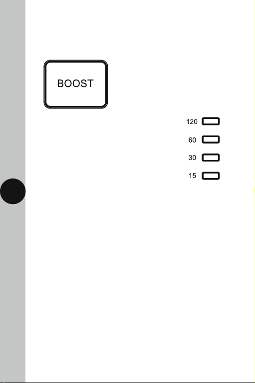
7. Manual Boost
• The manual boost is operated by pressing the BOOST button. When the
BOOST button is pressed, the button surround will illuminate, and the
selected time will be illuminated also.
• Press the BOOST button once for
15 minutes, twice for 30 minutes, three times
for 60 minutes or four times for 120 minutes.
Successive presses of the boost button
will scroll through the time periods.
• The boost can be cancelled by repeatedly pressing the boost button
6
until there is no boost light displayed.
• Should an economy period start within the duration of the boost,
this will override the boost period, using cheaper off peak electricity.
• During an off peak period, with the economy light illuminated,
it is not possible to use the boost function.
3 Year Guarantee
In the unlikely event of this product becoming faulty due to defective
material or manufacture within 3 years of the date of purchase, please
return it to your supplier in the first year with proof of purchase and it
will be replaced free of charge. For the second and third years or any
difficulty in the first year telephone the helpline on 020 8450 0515.
Note: A proof of purchase is required in all cases. For all eligible
replacements (where agreed by Timeguard) the customer is responsible
for all shipping/postage charges outside of the UK. All shipping costs
are to be paid in advance before a replacement is sent out.
Page 8

If you experience problems, do not immediately
Telephone the Timeguard Customer Helpline;
return the unit to the store.
HELPLINE
020 8450 0515
or email helpline@timeguard.com
Qualified Customer Support Co-ordinators will be on-line
to assist in resolving your query.
For a product brochure please contact:
Timeguard Limited.
Victory Park, 400 Edgware Road,
London NW2 6ND
Sales Office: 020 8452 1112
or email csc@timeguard.com
www.timeguard.com
Zerofour – November 2017
67.058.595 (Issue 1)
 Loading...