

Timeguard TRTD7N Installation & Operating Instructions Manual
Installation & Operating Instructions
Digital Economy Seven
Programmer
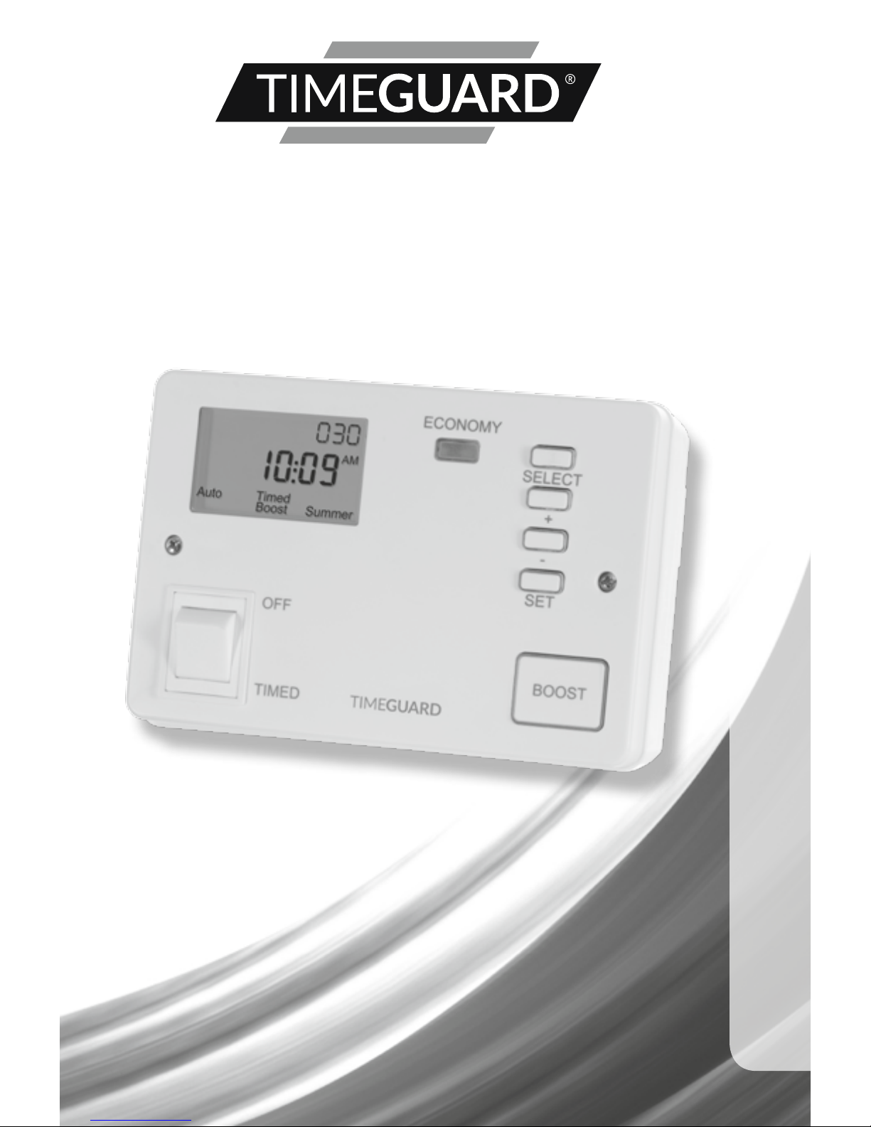
Model: TRTD7N – White

1
1. General Information
These instructions should be read carefully and retained for further reference
and maintenance.
2. Safety
• Before installation or maintenance, ensure the mains supply to the time
switch is switched off and the circuit supply fuses are removed or the
circuit breaker turned off.
• It is recommended that a qualified electrician is consulted or used
for the installation of this time switch and install in accordance
with the current IEE wiring and Building Regulations.
• Check that the total load on the circuit including when this
time switch is fitted does not exceed the rating of the circuit cable,
fuse or circuit breaker.
3. Technical Specifications
• 230V AC 50 Hz
• This time switch is of Class l Construction and must be earthed
• Switch Rating: 13A Resistive (3kW) Immersion Heaters
• Switch Type: Micro-disconnection ON control.
Disconnection to immersion heater(s)
via double pole rocker switch
• 24 hour Programme: 10 selectable pre-set tariff
programmes (0 – 9)
• Boost Times: 30, 60, 120 minutes
• Economy Output Light: Blue LED
• Battery Backup: 2 year reserve, factory fitted
rechargeable non-replaceable
• IP30 Rated suitable for restricted internal applications
• CE Compliant
• Dimensions (H x W x D): 111.5 x 170 x 60mm
2
3
4. Installation
Suitable for use with single, dual, or twin element immersion heaters.
4.1 Ensure the mains supply is switched off and the circuit supply fuses
are removed or the circuit breaker turned off.
4.2 Remove the 2 fixing screws holding the front panel to the back box.
4.3 Decide which mounting holes you would like to use and select a suitable
cable entry point by drilling into the back box ensuring not damage or
infringe on any of the internal components.
4.4 Mark the position of the mounting holes on the wall using the back
box as a template. Drill out the mounting holes taking care to avoid any
joists, electrical cables or water/gas pipes that may be hidden beneath
the surface. Insert the rawl plugs into the holes.
4.5 Pass the 230V 50Hz mains supply and load cables through the cable
entry point(s) on the back box.
4.6 Fix the back box to the wall using the correct mounting screws for the
rawl plugs installed.
4.7 Use the cable clamp in the back box to secure the cables.
4.8 Terminate the cables into the terminal block ensuring correct polarity
is observed and that all bare conductors are sleeved (See section 5.
Connection Diagram).
4.9 Select and set your preferred program and time setting using the
adjusters located on the reverse of the front panel (See section 6.
Commissioning).
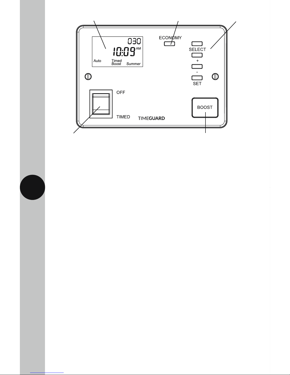
12 hour display (back lit during programming) Economy light Programming buttons
Boost button (illuminated in use)
OFF/Timed switch
12345
230V~50Hz
MAINS SUPPL
Y
LOAD
L
E
N
Heater
Neutral
Off Peak
Load
Earth
Link or
Bridge
Wire
3
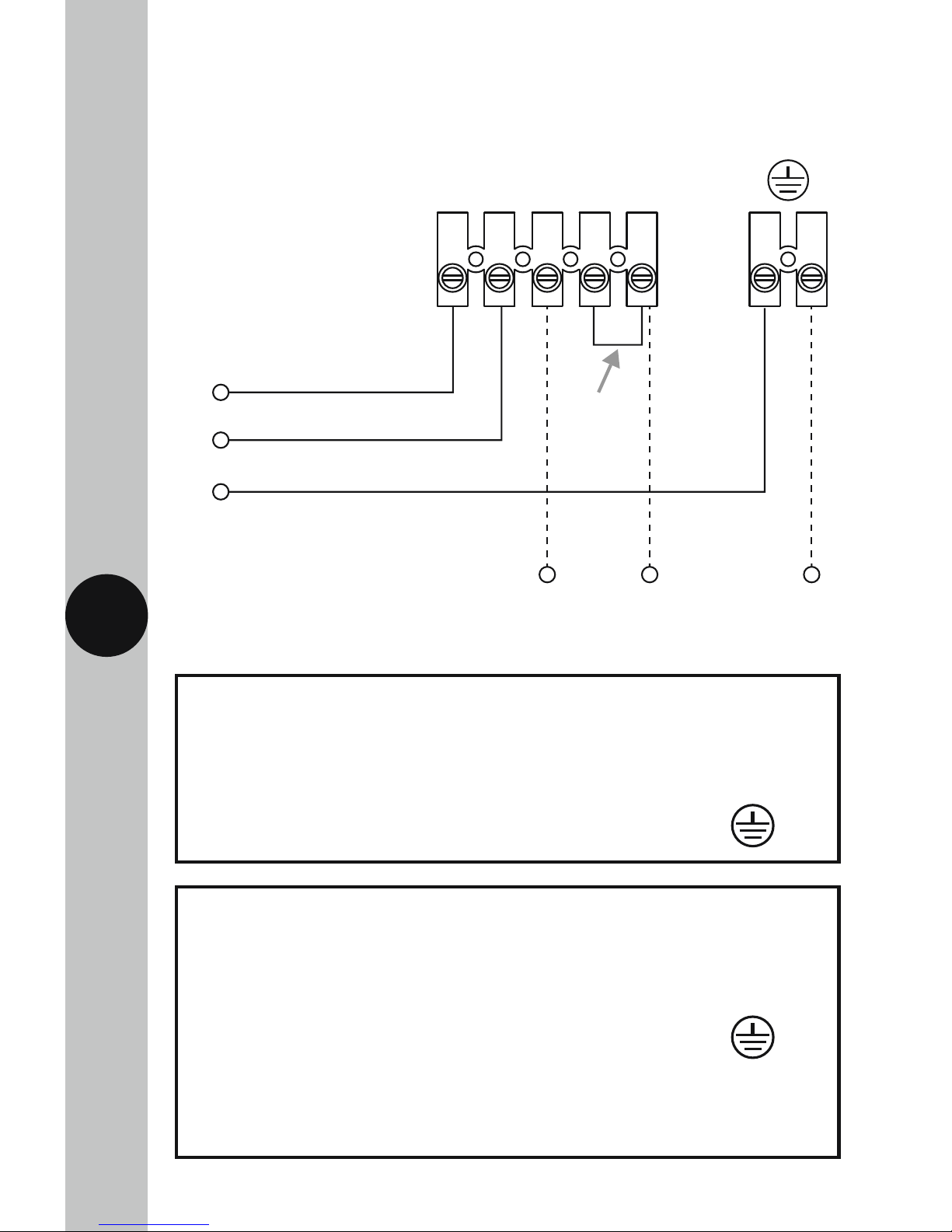
5. Connection Diagram
Connect the cables to the terminal block which are marked as follows;
• 230V 50Hz mains – Single element immersion heaters only.
230V 50Hz Mains Supply
Live Supply (Brown or Red) to terminal 1
Neutral Supply (Blue or Black) to terminal 2
Earth (Green/Yellow) to
Load
Switch Live, Off peak load (Brown or Red) to terminal 5
Heater Neutral (Blue or Black) to terminal 3
Earth (Green/Yellow) to
Note: a link or bridge will need to be fitted between terminal 4
and terminal 5 if you wish to use the Boost button
(single element immersion heaters only).

12345
230V~50Hz
MAINS SUPPL
Y
LOAD
L
E
N
Heater Neutral
Boost Load
Off Peak Load
Earth
4
• 230V 50Hz mains – Twin or Dual element immersion heaters.
230V 50Hz Mains Supply
Live Supply (Brown or Red) to terminal 1
Neutral Supply (Blue or Black) to terminal 2
Earth (Green/Yellow) to
Load
Switch Live, Off peak load –
Primary element (Brown or Red) to terminal 5
Switch Live, Boost load –
Secondary element (Brown or Red) to terminal 4
Heater Neutral (Blue or Black) to terminal 3
Earth (Green/Yellow) to
 Loading...