

Timeguard TRT047N Installation & Operating Instructions Manual
Installation & Operating Instructions
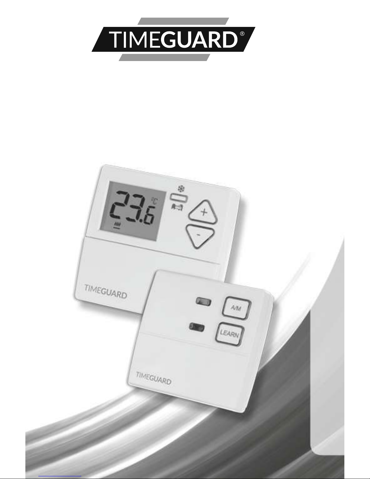
Wireless Digital Room
Thermostat with
Night Set-Back
Model: TRT047N

1
1. General Information
These instructions should be read carefully and retained for further reference
and maintenance.
2. Safety
• Before installation or maintenance, ensure the mains supply to the
thermostat is switched off and the circuit supply fuses are removed
or the circuit breaker turned off.
• It is recommended that a qualified electrician is consulted or used for the
installation of this thermostat and install in accordance with the current
IEE wiring and Building Regulations.
• Check that the total load on the circuit including when this thermostat is
fitted does not exceed the rating of the circuit cable, fuse or circuit breaker.
• To clean use a clean dry cloth only. Do not use any liquid cleaners.
3. Technical Specifications
Receiver
• 230V AC 50 Hz
• This thermostat is of Class ll Construction and must not be earthed
• Switch Rating: 3(1)A
• Switch Type: Single pole, voltage free
changeover contacts
• Connection Type: 3 wire
• Micro Disconnection: Type 1.B control action
• Illumination: Blue LED illuminated on setting
for button surrounds
• Output Light: Red LED
• Installation Type: Surface mount with wall plate
• CE Compliant
• Dimensions (H x W x D): 90 x 95 x 30mm
2
Transmitter
• Batteries: 2x 1.5V AA
• Operating Temperature Range: 0°C to +40°C
• Set Temperature Range: 10°C to 30°C
• Temperature Swing Adjuster: +/- 0.5°C or 1.0°C set by DIP switch
• PID Adjustment: ON or OFF set by DIP switch
• Boiler Type Adjustment: 3CYC = Gas, 6CYC = Oil, set by DIP switch
• Frost Protection Mode: 5°C
• Night Set Back Mode: Lowers set temperature
by 4°C for 1-9 hours
• Transmission: 868.3MHz
• Illumination: Blue LED illuminated on setting
for button surrounds and display
• Installation Type: Surface mount with wall plate
• CE Compliant
• Dimensions (H x W x D): 90 x 95 x 30mm
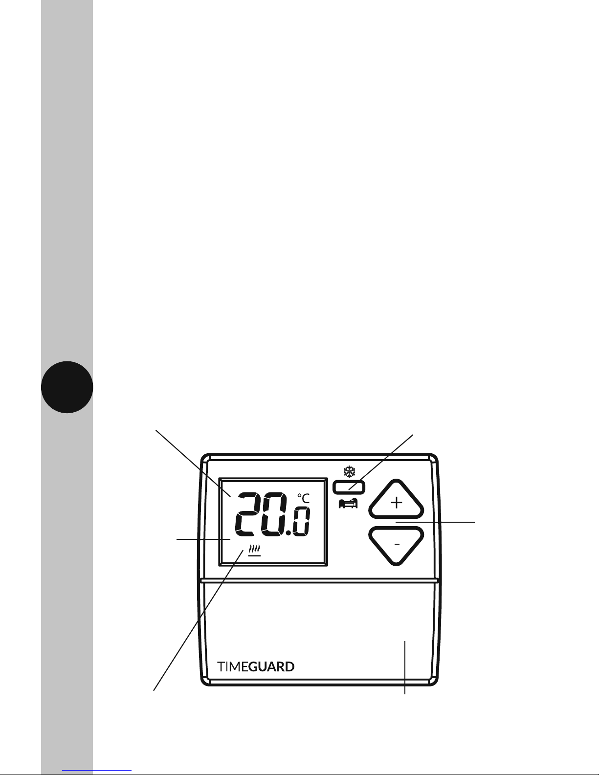
Transmitter Front View
Digital room temperature display
(illuminated on setting)
10°C to 30°C
set temperature
range
The heating symbol
will show when heat
is demanded
Night set-back (reduces temperature
by 4°C, 1-9 hours recall) and frost
protection setting mode
+/- setting
buttons
(illuminated
on setting)
Flip down cover for display battery
compartment and reset button –
uses 2x 1.5V AA batteries supplied
3
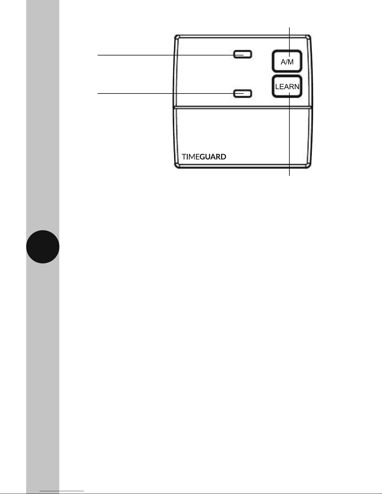
Learn/Manual Light,
Blue LED
Output ON light,
Red LED
Automatic/Manual mode button
Learn button enabling communication between the transmitter
and receiver, also control button for output in manual mode
Receiver Front View
4. Siting
Receiver
• The TRT047 Receiver should be mounted close to the items it will be
controlling i.e. boiler, control valves and pump.
• It should be mounted in a position where its control buttons and indicator
lights can be easily accessed.
Transmitter
• The TRT047N Transmitter must be sited where it will not be influenced
by heat sources, for example above a radiator or a television or
a refrigerator/freezer or in direct sunlight or subjected to draughts.
• The product requires air circulation, so do not position above
or below shelving or other wall mounted obstacles.
• It should be mounted approximately 1.5 metres above floor level.
5. Installation
Receiver
5.1 Ensure the mains supply is switched off and the circuit supply fuses are
removed or the circuit breaker turned off.
5.2 Remove the wall plate from the receiver unit, by undoing the retaining
screws, and pivoting the bottom of the unit outwards. The TRT047N
receiver body can then be lifted off.

4
Alternate mounting holes
Wall plate retaining screws
Retaining tabs
Mounting
holes
5.3 Mark the position of the mounting holes on the wall using the wall plate
as a template. Drill out the mounting holes taking care to avoid any
joists, electrical cables or water/gas pipes that may be hidden beneath
the surface. Insert the rawl plugs into the holes.
5.4 Pass the 230V 50Hz mains supply and load cables through the opening
of the wall plate. Allow sufficient excess cable to wire up the unit, but
not too much to make it difficult to close the unit to the wall plate.
5.5 Fix the wall plate to the wall using the correct mounting screws for the
rawl plugs installed. The retaining screws which secure the unit to the
wall plate should be at the bottom.
5.6 Terminate the cables into the terminal block ensuring correct polarity
is observed and that all bare conductors are sleeved (See section 6.
Receiver Connection Diagram). Make sure that the curved washer grips
the conductor.
5.7 To reinstall the unit onto the wall plate, first ensure the wall plate
retaining screws are loosened enough to clear the TRT047N receiver
body, then engage the top of the TRT047N receiver onto the wall plate
retaining tabs, and push firmly downwards and then upwards.
There will be some resistance from the terminals.
5.8 Once in place, secure with the retaining screws making sure
not to over tighten.
Receiver Wall Plate
 Loading...