

Page 1

Installation & Operating Instructions
7 Day Digital Programmer
1 Channel – Surface Mount
Model: TRT034N
Page 2

1
1. General Information
These instructions should be read carefully and retained for further reference
and maintenance.
2. Safety
• Before installation or maintenance, ensure the mains supply to the
Programmer is switched off and the circuit supply fuses are removed
or the circuit breaker turned off.
• It is recommended that a qualified electrician is consulted or used for the
installation of this Programmer and install in accordance with the current
IEE wiring and Building Regulations.
• Check that the total load on the circuit including when this Programmer is
fitted does not exceed the rating of the circuit cable, fuse or circuit breaker.
• To clean use a clean dry cloth only. Do not use any liquid cleaners.
3. Technical Specifications
• 230V AC 50 Hz
• This thermostat is of Class ll Construction and must not be earthed
• Switch Rating: 3(1)A
• Switch Type: Single pole, double throw (SPDT)
change over contacts
• Connection Type: 3 wire
• Installation Type: Surface mount with wall plate
• Micro Disconnection: Type 1.B control action
• Operating Temperature Range: 0°C to +40°C
• Programme: 5 day plus 2, or 7 day set by DIP switches
• Time Control Periods: 3 per day with copy function
• Clock Format: 12 hour AM/PM or 24 hour
• Summer/Winter Changeover: Day light saving, GMT or BST
• Holiday Mode: 0 to 31 day Programme suspension
• Boost Function: 1, 2 or 3 hour
Page 3
2
• Battery Backup: 7 Day, factory fitted rechargeable
(non-replaceable)
• Illumination: Blue LED illuminated on setting
for button surrounds and display
• CE Compliant
• Dimensions (H x W x D): 90 x 135 x 30mm
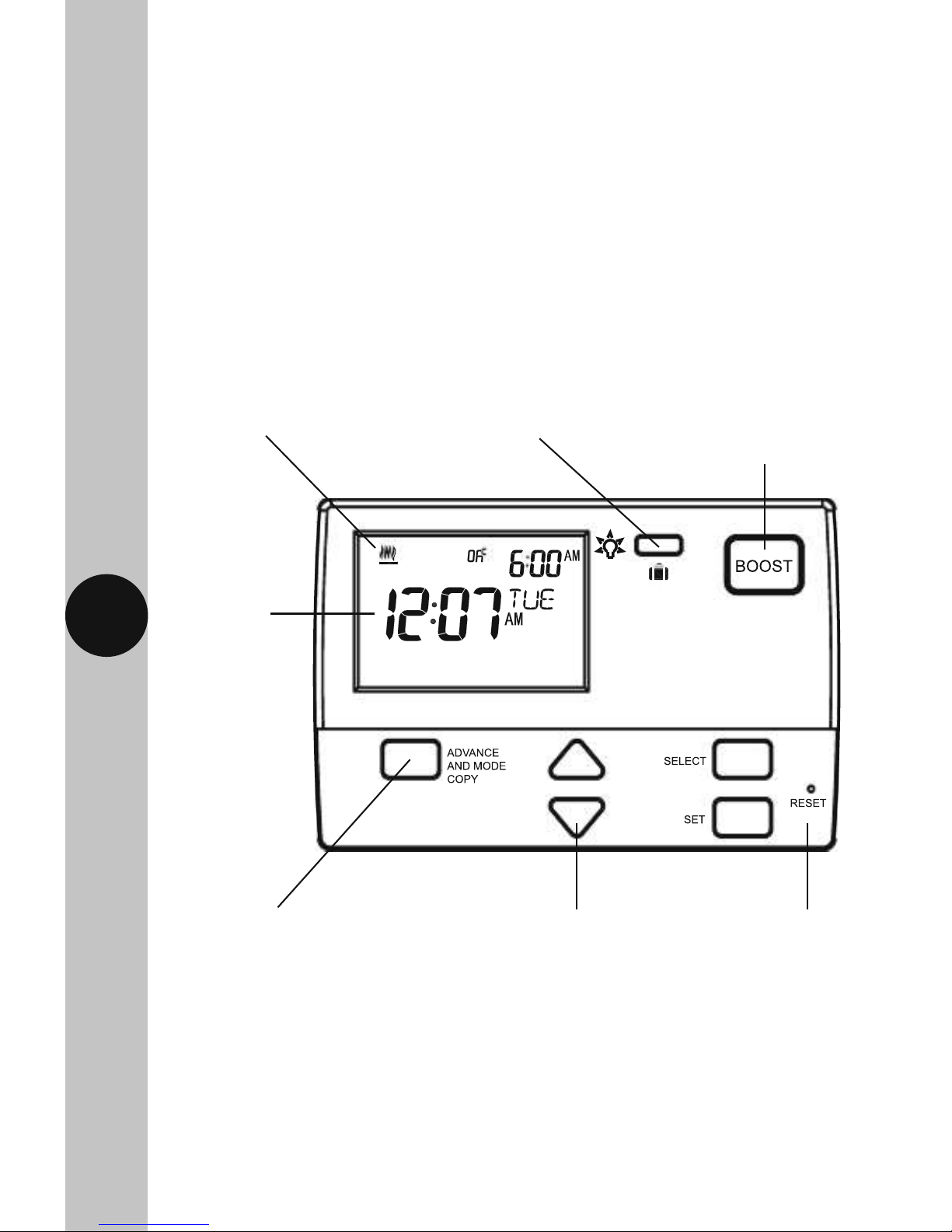
TRT034N Front View
The heating symbol will show
when heat is demanded
12hr am/pm
or 24hr clock
timer display
(illuminated
on setting)
Advance to next Programme,
ON/OFF override and copy function
Up down selection
buttons
1, 2 and 3 hour boost
function (illuminates
on setting)
Display light/Holiday
mode setting button
Flip down cover
conceals setting
buttons
Page 4

3
4. Siting
• The TRT034N should be located at a position which eases wiring runs
and gives good access for Programming.
• It should be mounted approximately 1.5m above floor level.
5. Installation
5.1 Ensure the mains supply is switched off and the circuit supply fuses
are removed or the circuit breaker turned off.
5.2 Remove the wall plate from the unit, by undoing the retaining screws,
and pivoting the bottom of the unit outwards. The TRT034N body can
then be lifted off.
5.3 Mark the position of the mounting holes on the wall using the wall plate
as a template. Drill out the mounting holes taking care to avoid any
joists, electrical cables or water/gas pipes that may be hidden beneath
the surface. Insert the rawl plugs into the holes.
5.4 Pass the 230V 50Hz mains supply and load cables through the opening
of the wall plate. Allow sufficient excess cable to wire up the unit, but
not too much to make it difficult to close the unit to the wall plate.
5.5 Fix the wall plate to the wall using the correct mounting screws for the
rawl plugs installed. The retaining screws which secure the unit to the
wall plate should be at the bottom.
5.6 Terminate the cables into the terminal block ensuring correct polarity
is observed and that all bare conductors are sleeved (See section 6.
Connection Diagram). Make sure that the curved washer grips
the conductor.
5.7 To reinstall the unit onto the wall plate, first ensure the wall plate
retaining screws are loosened enough to clear the TRT034N body,
then engage the top of the TRT034N onto the wall plate retaining tabs,
and push firmly downwards and then upwards. There will be some
resistance from the terminals.
5.8 Once in place, secure with the retaining screws making sure
not to over tighten.
Page 5
4
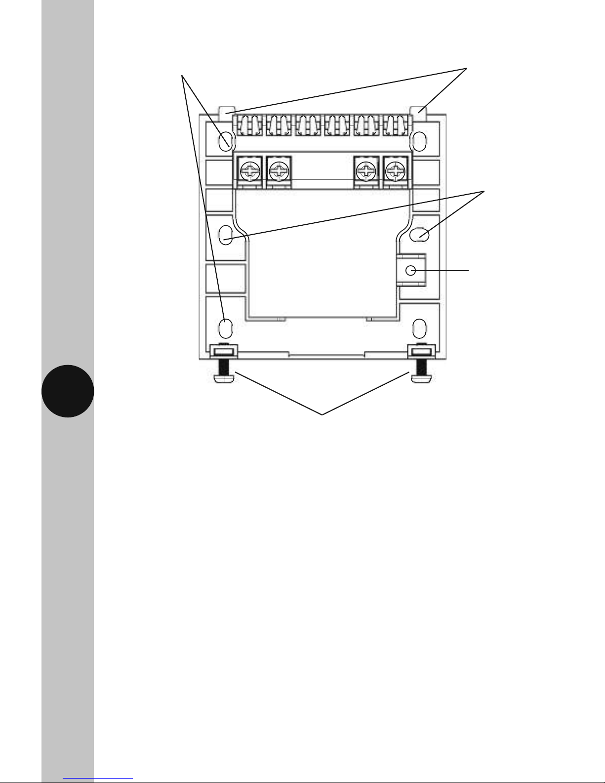
TRT034N Wall Plate
Alternate mounting holes
Wall plate retaining screws
Retaining tabs
Mounting
holes
Loop terminal
Page 6

NC
NO
BOILER
L
230V AC 50Hz
MAINS SUPPLY
Supply
Neutral
Supply
Live
N
Switch Live from NO
(normally open contact
for heating) to Boiler
5
6. Connection Diagram
Connect the 230V 50Hz mains supply and load cables to the terminal block
which are marked as follows;
• Note: Check boiler instructions before connecting.
230V 50Hz Mains Supply
Live Supply (Brown or Red) to L
Neutral Supply (Blue or Black) to N
A ‘Loop Terminal’ is provided should a 3 core cable
be used
Load (Boiler)
Switch Live (Brown or Red) to NO
Page 7

6
DIP switch position label
DIP switches for 5-2
or 7 day Programming
7. DIP Switch Settings
• Decide whether weekday/weekend (5-2) or individual (7) day programming
is required, and set the DIP switches in the correct position on the rear of
the unit. A reset will be required after changing the DIP switch positions.
TRT034N Rear of Unit
Page 8

7
8. Reset from Power-up
• Restore mains to the unit after making sure to check all system wiring
is complete, and after you have selected the desired DIP switch settings.
• Press the reset button located beneath the flip down cover on the front
of the unit, all of the characters will briefly appear on the display,
followed by the 12hr clock format screen.
• After 1 minute the screen will time out showing a default time
of 12:00AM.
• There are 3 timed controlled periods per day, and the default
Programmes are as follows;
Heating (HTG)
06:00AM ON
08:00AM OFF
10:00AM ON
12:00PM OFF
06:00PM ON
10:00PM OFF
9. Setting the Time and Date
9.1 To alter the time and date at any time, press and hold the Select button
for 3 seconds, the display light will illuminate.
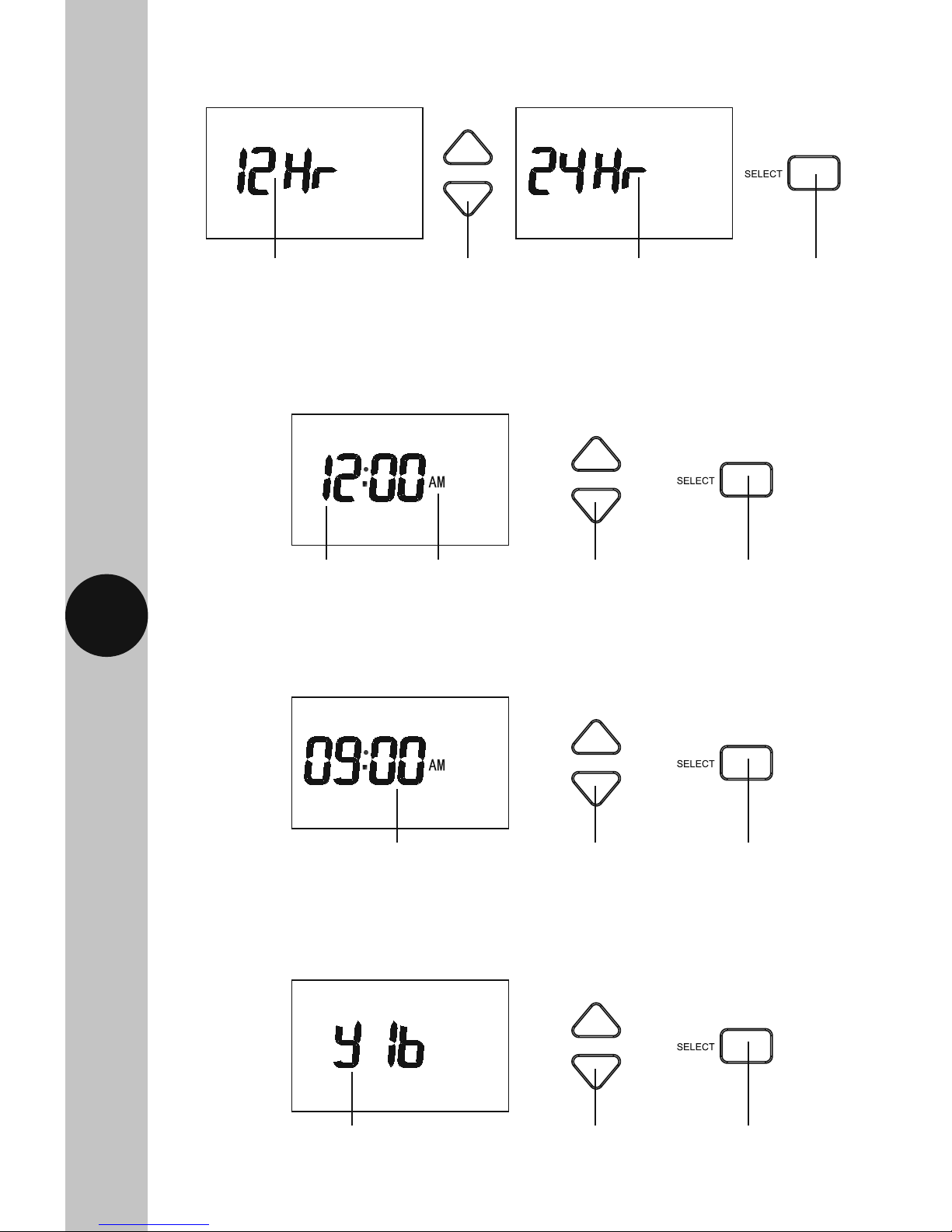
9.2 The default clock format is 12Hr which will be displayed on the screen.
Page 9
8
9.3 Use the Up/Down arrow buttons to either select 24Hr format, or leave
it at 12Hr format, and then press the Select button once to confirm.
9.4 The hour will to flash, use the Up/Down arrow buttons to alter the hour
and press the Select button once to confirm.
9.5 The minutes will flash, use the Up/Down arrow buttons to alter the
minutes and press the Select button once to confirm.
9.6 The year will flash, use the Up/Down arrow buttons to alter the year
and press the Select button once to confirm.
12Hr AM/PM format Use the Up/Down arrow
buttons to change
the time format
24Hr format Use the Select
button to
confirm
Use the Up/Down
arrow buttons to
change the hour
The hour will flash Example of
12Hr AM/
PM format
Use the Select
button to
confirm
Use the Up/Down
arrow buttons to
change the minutes
The minutes will flash Use the Select
button to
confirm
Use the Up/Down
arrow buttons to
change the year
The year will flash Use the Select
button to
confirm
Page 10

9
9.7 The month will flash, use the Up/Down arrow buttons to alter the year
and press the Select button once to confirm.
9.8 The day will flash, use the Up/Down arrow buttons to alter the day
and press the Select button once to confirm.
9.9 The daylight saving option (GMT=OFF/BST=ON) will flash, by default this will
be set to OFF. Use the Up/Down arrow buttons to alter the setting. Press the
Select button once to confirm and return to re-enter the date and time from
the beginning, or press the Set button once to confirm and exit.
Use the Up/Down
arrow buttons to
change the month
The month will flash Use the Select
button to
confirm
Use the Up/Down
arrow buttons to
change the day
The day will flash Use the Select
button to
confirm
The DLS will flash,
OFF for GMT by
default
The DLS set to
ON for BST
Use Set to
confirm
and exit
Use Select to confirm
and return to re-enter
time & date
Main screen
showing day,
time and
output status
Note:
• If no button is pressed, it will time out after 60 seconds and return to the
mains screen showing day, time and output status.
• The display light will also time out after 15 seconds after the last button
is pressed.
• The Set button can be pressed to exit the date and time entry at any stage.
Page 11

10
10. Programme Entry
Note:
• If you have selected weekday/weekend (5-2) Programming via the DIP
switches (see section 7. DIP Switch Settings) you will be able
to group Monday – Friday for the same ON and OFF times,
and then group Saturday – Sunday for the same ON and OFF times.
• If you have selected individual (7) day Programming via the DIP switches,
then you will need to set ON and OFF times for each day of the week,
Monday through to Sunday, for each day you require.
• The Copy function can be used to duplicate ON and OFF times for different
days of the week, as detailed further in the instructions
(read the instructions in full before you begin).
The following steps use the individual (7) day Programming as an example.
The steps for weekday/weekend (5-2) Programming are the same,
except you will be able to select either M – F (Monday to Friday grouped)
or S – S (Saturday and Sunday grouped), instead of individual days.
10.2 The Day of the week will flash (e.g. Mon), use the Up/Down arrow
buttons if you need to choose a different day of the week, and then
press the Select button once to confirm.
10.1 Press and hold the Set button for 3 seconds to enter the Programming
mode, the display light will illuminate.
Use the Up/Down arrow
buttons to change the
day of the week
Mon will flash
when selected
Use the Select
button to
confirm
Page 12

11
10.3 The P1 ON (Programme 1 ON) hour will flash, use the Up/Down arrow
button to choose the hour and press the Select button once to confirm.
10.4 The minutes will flash, use the Up/Down arrow button to choose the
minutes and press the Select button once to confirm.
10.5 The P1 OFF (Programme 1 OFF) hour will flash, use the Up/Down arrow
button to choose the hour and press the Select button once to confirm.
10.6 The minutes will flash, use the Up/Down arrow button to choose the
minutes and press the Select button once to confirm.
10.7 The P2 ON (Programme 2 ON) hour will flash. Follow steps ‘10.3’
to ‘10.6’ for P2 (Programme 2 ON and OFF) and also P3
(Programme 3 ON and OFF).
10.8 Press the Set button once to change the day of the week (e.g. Tue).
Use the Up/Down Arrows to choose the day of the week, and press
the Select button once to confirm.
10.9 Follow steps ‘10.3’ to ‘10.8’ until you have Programmed each day
of the week that you require.
10.10 Press the Set button twice to exit the Programme entry.
Use the Up/Down
arrow buttons to
change the hour
The hour will flash Use the Select
button to
confirm
Note:
• If no button is pressed, it will time out after 60 seconds and return to the
mains screen showing day, time and output status.
• The display light will also time out after 15 seconds after the last button
is pressed.
• All 3 time controlled periods will need to be Programmed, unwanted times
need to be entered as the same time i.e. P2 ON 7:00AM, P2 OFF 7:00AM.
P3 ON 7:00AM, P3 OFF 7:00AM.
Page 13

12
10.11 From the main screen, press and hold the Set button for 3 seconds,
so the day of the week is flashing e.g. Mon (or if you are already
in the programming screen, press Set once so the day flashes).
10.12 Press the Advance and Mode Copy button once. Use the Up/Down
arrow buttons to choose the day of the week you wish to copy,
and press the Select button once.
The day of the week
will flash e.g. Mon
Press and hold the
Set button for 3
seconds
Copy and the day of
the week will flash
Press the Advance
and Mode copy
button once
Use the Up/Down
arrow button if you
wish to change the
day of the week
to copy
• Unwanted days of the week need to be entered as the same time i.e. Wed
P1-P2-P3 ON 7:00AM, P1-P2-P3 OFF 7:00AM. Thu P1-P2-P3 ON 7:00AM,
P1-P2-P3 OFF 7:00AM etc.
• The Set button can be pressed twice to exit the programme entry
at any stage.
Copy Function
Note:
• The copy function can only be used after you have programmed at least
one day.
Page 14

13
10.13 Use the Up/Down arrow buttons to choose the day of the week you
wish to copy the Programme to e.g. Tue, and press the Select button
once to confirm.
10.14 Use the Up/Down arrow buttons to choose the next day of the week
you wish to copy the Programme to e.g. Wed, and press the Select
button once to confirm.
10.15 Repeat step 10.14 until you have copied the programme to all
of the days of the week that are required.
10.16 Press the Set button twice to exit the programme entry.
Note:
• If no button is pressed, it will time out after 60 seconds and return
to the mains screen showing day, time and output status.
• The display light will also time out after 15 seconds after the last
button is pressed.
• The Set button can be pressed twice to exit the copy function
at any stage.
Copy and the day of
the week will flash
Use the Up/Down arrows to
choose the day you wish to copy
the Programme to e.g. Tue
Use the Select button
to confirm and copy
the Programme
Copy and the day of
the week will flash
Use the Up/Down arrows to
choose the next day you wish to
copy the Programme to e.g. Wed
Use the Select button
to confirm and copy
the Programme
Page 15

14
11. Operation
Programme Modes
• There are 4 Programme modes available. You can cycle through all
4 Programme modes by pressing the Advance and Mode Copy button.
The output status will be as follows;
Press the Advance and Mode Copy
button to cycle through the
4 Programme modes.
Always OFF
Always ON
OFF until next ON
ON until next OFF
Permanent OFF
Permanent ON
OFF until next
programmed ON
ON until next
programmed OFF
Page 16
15
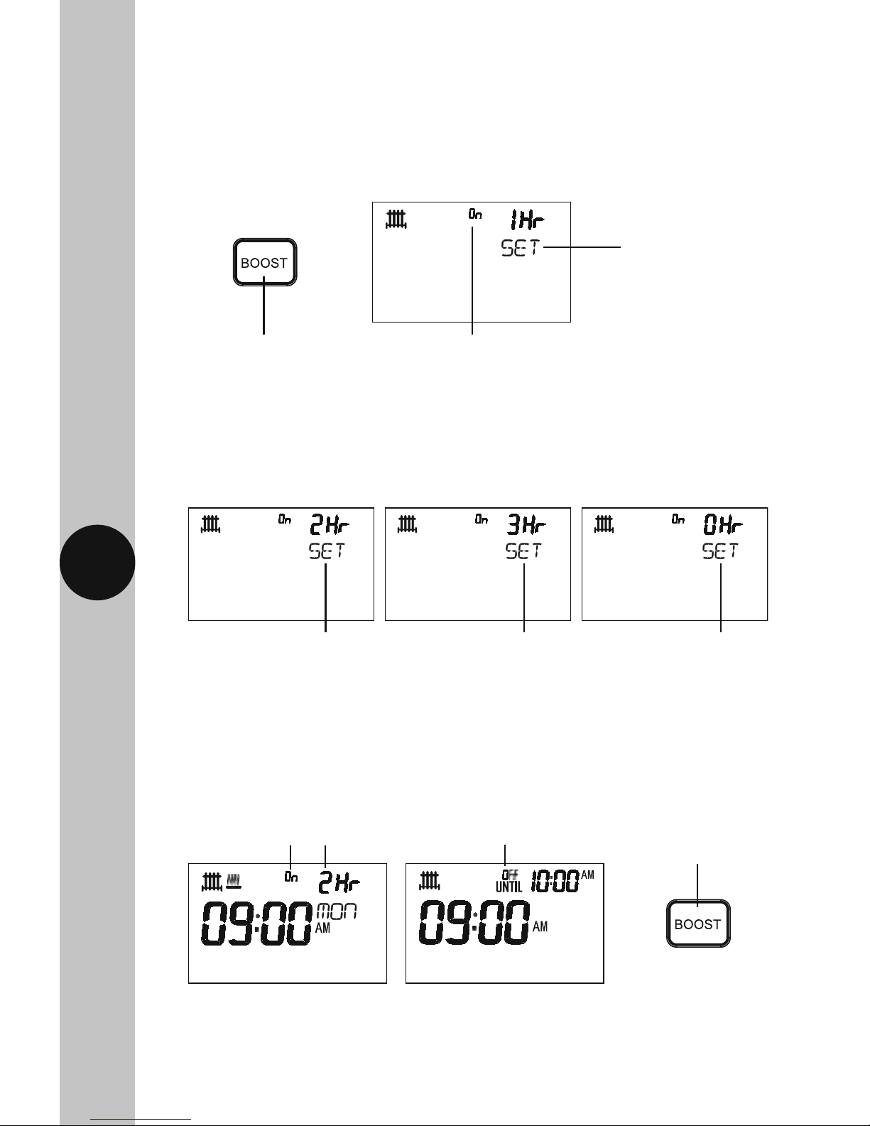
On will flash ON and OFF
whilst setting, and during the
boost period
The display light
will illuminate and
1hr SET will appear
on the screen
Press the Boost button,
the button surround will
illuminate
Display showing 2hr boost
period with On flashing after
the boost setting times out
Display showing normal
operation when boost is
cancelled
The Boost button
surround will
remain illuminated
whilst active
Boost Function
• The boost options are 1 hour, 2 hours, 3 hours and 0 hours to cancel.
• Press the Boost button once for 1 hour, the display light will illuminate
as well as the Boost button surround. While setting, and during
the boost period, the On flashes ON and OFF.
• A second press of the Boost button will increase the timed period to
2 hours, a third press for 3 hours and a fourth press for 0 hours, which will
cancel the boost timed period and return you to normal operation.
• The boost setting will time out after 15 seconds, and the display light will
turn OFF. The Boost button surround will remain illuminated whilst active.
2 presses of the
Boost button for
2 hours
3 presses of the
Boost button for
3 hours
4 presses of the Boost
button for 0 hours
to cancel the boost
timed period
Page 17

16
Display Light/Holiday Button
• Pressing the Display light/Holiday button once illuminates the display
for 15 seconds.
• Set the number of day’s holiday using the Up/Down arrow buttons.
This can be between 0 to 31 days. The day number will flash during
setting, and the suitcase symbol will appear. Press the Set button once
to confirm and exit, or confirm and exit by leaving the screen to time out
after 15 seconds.
• Any key press will illuminate the screen also, with a 15 second
time out after the last button press.
• Any time the back light is on, the Display light/Holiday button
surround illuminates.
Holiday Mode
• Press the Display light/Holiday button and hold for 3 seconds.
Use the Up/Down
arrows to set the
number of days
The day number will flash,
and the suitcase symbol
will appear
Use the Set
button to
confirm and exit
Page 18

17
• The holiday duration will be displayed in the top right had corner
of the screen.
• To cancel the holiday, press the Display light/Holiday button and hold
for 3 seconds. The holiday duration and suitcase symbol will disappear.
Holiday duration
Suitcase symbol
Page 19

18
3 Year Guarantee
In the unlikely event of this product becoming faulty due to defective
material or manufacture within 3 years of the date of purchase, please
return it to your supplier in the first year with proof of purchase and it
will be replaced free of charge. For the second and third years or any
difficulty in the first year telephone the helpline on 020 8450 0515.
Note: A proof of purchase is required in all cases. For all eligible
replacements (where agreed by Timeguard) the customer is responsible
for all shipping/postage charges outside of the UK. All shipping costs
are to be paid in advance before a replacement is sent out.
Page 20

Zerofour – January 2018
67.058.601 (Issue 1)
Timeguard Limited.
Victory Park, 400 Edgware Road,
London NW2 6ND
Sales Office: 020 8452 1112
or email csc@timeguard.com
For a product brochure please contact:
HELPLINE
020 8450 0515
or email helpline@timeguard.com
www.timeguard.com
Qualified Customer Support Co-ordinators will be on-line
to assist in resolving your query.
If you experience problems, do not immediately
return the unit to the store.
Telephone the Timeguard Customer Helpline;
 Loading...