

Page 1
Electronic Room
Thermostat
Cat. No. TRT030
Operating & Installation Instructions
Page 2

What is a room thermostat?
...an explanation for householders
A room thermostat simply switches the heating
system on and off as necessary. It works by
sensing the air temperature, switching on the
heating when the air temperature falls below
the thermostat setting, and switching it off
once this set temperature has been reached.
Turning a room thermostat to a higher setting
will not make the room heat up any faster.
How quickly the room heats up depends on the
design of the heating system, for example, the
size of boiler and radiators.
Neither does the setting affect how quickly the
room cools down. Turning a room thermostat to a
lower setting will result in the room being controlled
at a lower temperature, and saves energy.
The heating system will not work if a time
switch or programmer has switched it off.
The way to set and use your room thermostat
is to find the lowest temperature setting
that you are comfortable with, and then
leave it alone to do its job. The best way to
do this is to set the room thermostat to a
low temperature – say 18ºC – and then
turn it up by one degree each day until
you are
You won’t have to adjust the thermostat further.
Any adjustment above this setting will waste
energy and cost you more money.
If your heating system is a boiler with radiators,
there will usually be only one room thermostat
to control the whole house. But you can have
different temperatures in individual rooms by
installing thermostatic radiator valves (TRVs)
on individual radiators. If you don’t have TRVs,
you should choose a temperature that is
reasonable for the whole house. If you do
have TRVs, you can choose a slightly higher
setting to make sure that even the coldest room
is comfortable, then prevent any overheating in
other rooms by adjusting the TRVs.
comfortable with the temperature.
Room thermostats need a free flow of air to
sense the temperature, so they must not be
®
covered by curtains or blocked by
furniture. Nearby electric fires, televisions,
wall or table lamps may prevent the
thermostat from working properly.
Page 3

1. Introduction
TRT030 Electronic Room Thermostat
TRT products are a cost effective
comprehensive range of thermostats and
timers designed for internal use only.
The TRT030 is an electronic room
thermostat, with an easily adjustable dial.
It has optional PID control (which can help
to minimise temperature overshoot), and
adjustable swing (difference between on
and off switching temperatures), from
1ºC to 0.5ºC.
It is designed to be surface mounted
on its supplied wall plate.
The electrical supply must be isolated
before removing the thermostat from
the wall plate.
Output LED
Clearly
marked scale
Fig. 1
Easy set dial
Stylish design
Page 4

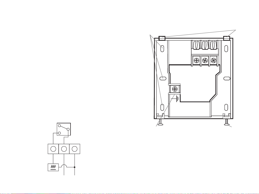
Rear View of TRT030
(without mounting plate)
Multiple fixing
holes
Fig. 2
Wiring terminals Earth terminal
PID
SWING
ON OFF
1.0 0.5
Swing Jumper
(shown in Swing
0.5 position)
Wall plate retaining screws
(at bottom of TRT030)
Contents
TRT030 thermostat
TRT030 instruction
leaflet
PID Jumper
(shown in PID
off position)
TRT030 wall plate
2 x wall plugs
2 x screws
2. Siting
The TRT030 must be sited where it will not be
influenced by heat sources, for example above
a radiator or a television or in direct sunlight
or subjected to draughts.
The product requires air circulation, so do not
position above or below shelving or other wall
mounted obstacles.
It should be mounted approximately 1.5 meters
above floor level.
3. Installation
This product should be installed by a qualified
installer to current installation standards.
If in any doubt contact the Timeguard Helpline
020 8450 0515.
The TRT030 is designed to be surface mounted
on the supplied wall plate (Fig. 4).
Always isolate the mains supply before
removing the unit from its wall plate.
Isolate 230VAC mains supply.
Incoming and outgoing wires should be
1.5mm sq.
Page 5
Remove wall plate from unit, by undoing
retaining screws (see Fig. 2), and pivoting the
bottom of the unit outwards. The TRT030 can
then be lifted off.
Pass the incoming wires through the opening in
wall plate, and fix wall plate securely to the wall,
using the screws provided (and wall plugs if
necessary) provided. The screws which secure
the product to the wall plate should be at the
bottom (see Fig. 2).
Allow sufficient excess cable to wire up the unit,
but not too much to make it difficult to close
the unit to the wall plate.
Connect the conductors to the relevant terminals,
according to the wiring diagram on the wall
plate (or Fig. 3 below). Ensure that the curved
brass washer grips the conductor.
Back Plate Removed
Alternative
fixing holes
Retaining
tabs
NO NL
Wiring
Diagram
Note:
Check boiler
instructions
before
connecting.
Fig. 3
NO NL
Terminal for maintaining
continuity of earth
Mount the wall plate in this
Fig. 4
configuration only
Product retaining
screws
This unit is double insulated, and hence does not
need connection to earth. If earth continuity is
N
L
required, please use earth terminal on wall plate.
Page 6

To reinstall the unit on the wall plate first
ensure the wall plate retaining screws are
loosened enough to clear the TRT030 body
then engage the top of the TRT030 onto the
wall plate retaining tabs (see Fig. 4), and push
firmly downwards and then upwards. There will
be some resistance from the terminals. Once in
place, secure with the retaining screws.
Restore mains to the unit after checking all
system wiring is complete.
4. Operation
Use adjuster dial to set desired temperature.
Blue LED is lit when temperature is below
desired value, indicating that the thermostat is
calling for heat from the boiler. Once the room
reaches the desired temperature the LED turns
off and the TRT030 ceases to call for heat from
the boiler.
The temperature swing can be adjusted between
1°C and 0.5°C by selecting a jumper found on
the rear of the unit (see Fig. 2).
We suggest using the 0.5ºC position unless the
boiler turns on and off too rapidly.
PID can also be selected on or off using a
jumper on the rear of the unit (see Fig. 2).
This can help in reducing temperature over-shoot.
We suggest using the PID on position.
To clean use a clean dry cloth only. Do not use
any liquid cleaners.
5. Specifications
Current rating: 6 (2) A
Voltage: 220-240V, 50HZ
Switch type: Single pole, single throw
(SPST)
Operating
temperature range: 0°C to 50°C
Set temperature
range: 5°C to 30°C
Complies with: BS EN 60730
Conforms to
directives: Conforms to latest directives
Temperature
swing: 1°C or 0.5°C
Micro
disconnection: Type 1.B control action
Page 7

For assistance with the product please contact:-
HELPLINE
020 8450 0515
or email helpline@timeguard.com
3 Year Guarantee
In the unlikely event of this product becoming
faulty due to defective material or manufacture
within 3 years of the date of purchase, please
return it to your supplier in the first year with proof
of purchase and it will be replaced free of charge.
For years 2 and 3 or any difficulty in the first year
telephone the helpline on
Note: a proof of purchase is required
in all cases. For all eligible replacements (where agreed by
Timeguard Ltd) the customer is responsible for all shipping/
postage charges for sending replacements outside the UK.
All shipping costs are to be paid in advance before
a replacement is sent.
For a product brochure please contact:
Timeguard Ltd. Victory Park, 400 Edgware Road,
London NW2 6ND Tel: 020 8452 1112
or email csc@timeguard.com
A Group company
67-058-322 (issue 3)
020 8450 0515.
 Loading...