

Page 1
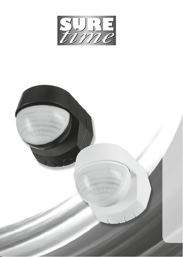
180° PIR Light Controller
Model: STLB1000 – Black
Model: STLW1000 – White
I n s tallation & Operating Instructions
Page 2

1
1. General Information
These instructions should be read carefully and retained for further reference
and maintenance.
2. Safety
• Before installation or maintenance, ensure the mains supply to the PIR
light controller is switched off and the circuit supply fuses are removed
or the circuit breaker turned off.
• It is recommended that a qualified electrician is consulted or used for
the installation of this PIR light controller and install in accordance
with the current IEE wiring and Building Regulations.
• Check that the total load on the circuit including when this PIR light controller
is fitted does not exceed the rating of the circuit cable, fuse or circuit breaker.
Page 3

2
3. Technical Specifications
• 230V AC 50 Hz
• This PIR light controller is of class II construction and must not be earthed
• Motion Detection Range: Up to 8 to 12 metres
at a 2.5m mounting height
• Detection Angle: 180°
• Maximum Switching Load: 1000W Halogen lighting,
200W Fluorescent & LED lighting
• Time ON Adjustment: 3 seconds to 18 minutes.
• Dusk Level Adjustment: 10 to 1000 Lux, Day and night
or night time only operation
• Pan/Tilt Adjustment: Pan left and right 45°, Tilt down 35°
• Manual Override: 6 hours max
• Warm-up Time: 60 seconds
• Operating Temperature: -20°C to + 40°C
• IP55 Rated suitable for restricted external applications
• CE Compliant
• Dimensions: H=76mm, W=76mm, D=87mm
• Multiple PIR light
controller switching: A maximum of 5 STLB/W1000 PIR light
controllers can be wired in parallel,
to enable any detector to turn ON
all the lights connected.
The total load must not exceed the lamp
rating of a single STLB/W1000 unit.
Page 4
3
4. Selecting a Location
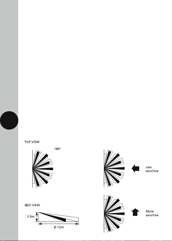
• The motion detector has number of detection zones, at various vertical and
horizontal angles as shown (See image “A”).
• The best all-round coverage is achieved with the unit mounted at the optimum
height of 2.5 metres.
• Careful positioning of the sensor will be required to ensure optimum
performance (see image “A” and “B” detailing detection range and direction).
• The sensor is more sensitive to movement ACROSS its field of vision than
to movement directly TOWARDS (See image “B”). Therefore position the unit
so that the sensor looks ACROSS the likely approach path.
• Avoid positioning the sensor where there are any sources of heat in the
detection area (extractor fans, tumble dryer exhausts etc.) including opposite
any other light sources such as other security lights.
• Reflective surfaces (i.e. pools of water or white painted walls) and overhanging
branches may cause false activation under extreme conditions.
• During extreme weather conditions the motion sensor may exhibit unusual
behaviour. This does not indicate a fault with the PIR light controller. Once normal
weather conditions return, the sensor will resume normal operation.
A B
Page 5
4
5. Installation
• Ensure the mains supply is switched off and the circuit supply fuses
are removed or the circuit breaker turned off.
• An isolating switch should be installed to enable the power to be switched
ON and OFF for maintenance purposes and to activate the manual/auto
override function.
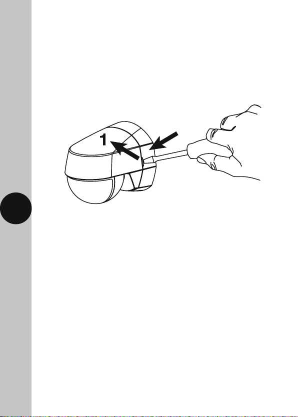
• Remove the back plate from the PIR light controller.
Insert flat blade screwdriver under
tab and lever in direction 1
• Mark the position of the mounting holes using the back plate as a template.
Drill out the mounting holes taking care to avoid any joists, electrical cables
or water/gas pipes that may be hidden beneath the surface.
Insert the rawl plugs into the holes.
• Pass the 230V 50Hz mains supply and load cables through the cable entry
point on the back plate, ensuring the grommet(s) is used to maintain the
IP rating of the PIR light controller.
• Fix the back plate to the wall. Take care not to over-tighten the screws
to prevent damage to the back plate. If using a power screwdriver,
use the lowest torque setting.
Page 6
5
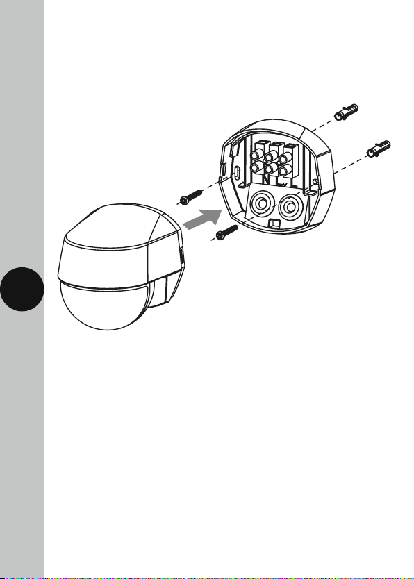
• Terminate the cables into the terminal block ensuring correct polarity
is observed and that all bare conductors are sleeved
(See section 6. Connection Diagram).
• Line the PIR light controller up with the back plate, apply pressure to both sides
of the unit until both catches click into place to ensure a weatherproof seal.
Page 7
6
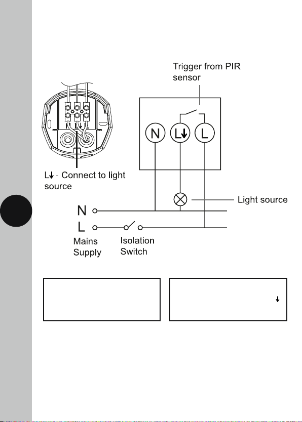
6. Connection Diagram
• Connect the 230V 50Hz mains supply and load cables
into the terminal block as follows;
230V 50Hz Mains Supply
Live Supply (Brown or Red) to L
Neutral Supply (Blue or Black) to N
Load (Light Source)
Switch Live (Brown or Red) to L
Neutral Load (Blue or Black) to N
Page 8
7
7. Walk Test Procedure (Test Mode)
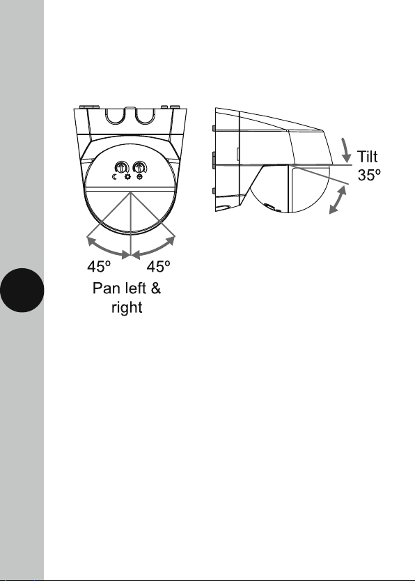
• The sensor will rotate from left to right, and can tilt downwards.
Adjust the sensor to point in the required direction and angle down
to limit forward range as required.
• The adjustment knobs located beneath the PIR light controller are factory set
to “Walk Test Mode”. Double check they are set as follows;
Time ON setting – fully anti-clockwise
Dusk (Lux) level setting – fully clockwise
• Turn the power to the unit ON. The lamp will immediately illuminate as the unit
goes through its “warm-up” period. After approximately 1 minute the lamp will
extinguish. This indicates the unit is wired correctly and the unit is in Test Mode.
• Try to remain outside the detection area during the warm-up period.
• The unit will now operate during daytime as well as at night, illuminating the
lamp for approx. 3 seconds each time. This allows testing to be carried out to
establish whether the sensor is covering the required area.
Page 9

8
• Walk across the detection area. Each time you are detected the lamp
will illuminate.
• Now stand still until the lamp extinguishes (this should take approx. 3 seconds).
Start moving again after 2 seconds, and the lamp will illuminate.
• Repeat the above, walking at various distances and angles to the unit.
This will help you to establish the detection pattern.
• If the detection area is too small for your requirements, try angling the sensor
head up. Angling the head downwards will reduce the detection area should
a smaller range be required.
8. Setting Up for Automatic Operation
(Auto Mode)
• When the walk tests are complete, the unit can be adjusted for
automatic operation.
• The Time ON setting controls how long the unit remains illuminated following
activation and after all motion ceases.
• The minimum time (fully anti-clockwise) is approx. 3 seconds, whilst the
maximum time (fully clockwise) is approx. 18 minutes. Set the control
to the desired setting between these limits.
• The Dusk (Lux) level setting determines the level of darkness required for the
unit to start operating. The setting is best achieved by the procedure below;
1. Set the Dusk (Lux) level control knob fully clockwise.
2. When the ambient light level reaches the level of darkness at which you wish
the lamp to become operative (i.e. at dusk) SLOWLY rotate the control knob in
an anti-clockwise direction until a point is reached where the lamp illuminates.
3. Leave the control knob set at this point.
• At this position the unit should become operative at approximately the same
level of darkness each evening.
• Observe the operation of the unit. If the unit is starting to operate too early
(i.e. when it is quite light) adjust the control knob slightly anti-clockwise.
If the unit starts to operate too late (i.e. when it is very dark).
Adjust the control knob slightly clockwise.
• Continue to adjust until the unit operates as desired.
Page 10

9
9. Manual Override Mode
The light can be switched ON for longer time periods by use of the Manual
Override Mode. This can be activated at night by using the isolation switch.
• Switch the isolation switch once (OFF/ON) within 1.5 seconds.
• The unit will now illuminate continuously for approximately 6 hours
or until it is switched back into Auto Mode.
• To return to Auto Mode switch the isolation switch OFF and then
back ON again within 1.5 seconds.
10. Troubleshooting
Problem
• The lamp stays ON
at night.
• The PIR keeps
activating for no
reason at random.
Solution
Cover the PIR lens with a thick cloth. If the light
turns OFF, check the detection area for heat or a
reflective source. If the light stays ON, check the wiring
(See section 6. Connection Diagram).
Turn OFF at the isolation switch. Turn back ON again
after 30 seconds. Leave for approximately 15 minutes.
If the light activates, check for false activation from
heat, wind or a reflective source.
• The PIR will not
operate at all.
Check that the power is switched ON at the power
supply or isolation switch.
Turn OFF the power to the unit and check the wiring
connections. Check the lamp (if it’s changeable). If the
lamp has failed, replace. Ensure the lamp is seated
correctly in the lamp-holder. Please note that the unit
will not detect through glass (e.g. in a glazed porch).
Page 11

• The PIR sensor will
not operate at night.
The level of ambient light in the area may be
too bright to allow operation at the current
Dusk (Lux) level setting.
During the hours of darkness, adjust the Dusk (Lux)
level control knob slowly anti-clockwise until the lamp
illuminates.
10
• The PIR coverage
is poor/sporadic.
The PIR may be poorly located (See section 4. Selecting
a location) and re-locate the unit.
2 Year Guarantee
In the unlikely event of this product becoming faulty due to defective material or
manufacture within 2 years of the date of purchase, please return it to your supplier
in the first year with proof of purchase and it will be replaced free of charge.
For the second year or any difficulty in the first, telephone the helpline
on 020 8450 0515.
Note: A proof of purchase is required in all cases. For all eligible replacements (where
agreed by Timeguard) the customer is responsible for all shipping/postage charges
outside of the UK. All shipping costs are to be paid in advance before a replacement
is sent.
Page 12

If you experience problems, do not immediately return the unit
to the store. Telephone the Timeguard Customer Helpline;
HELPLINE
020 8450 0515
or email [email protected]
Qualified Customer Support Co-ordinators will be on-line
to assist in resolving your query.
Deta Electrical Co Ltd
Panattoni Park, Luton Road,
Chalton, Bedfordshire, LU4 9TT
Sales Office: 020 8452 1112
or email [email protected]
TW – August 2023
www.timeguard.com
67.058.587 (Issue 3)
 Loading...