

Page 1
Mini Recessed PIR
Model: PDFM360MINI
Installation & Operating Instructions
Page 2

1. General Information
These instructions should be read carefully and retained for further reference
and maintenance.
2. Safety
• Before installation or maintenance, ensure the mains supply to the PIR sensor
is switched off and the circuit supply fuses are removed or the circuit breaker
turned off.
• It is recommended that a qualified electrician is consulted or used for the
installation of this PIR sensor and install in accordance with the current
IEE wiring and Building Regulations.
• Check that the total load on the circuit including when this PIR sensor is fitted
does not exceed the rating of the circuit cable, fuse or circuit breaker.
3. Technical Specifications
• 230V AC 50 Hz
• This PIR sensor is of Class ll Construction and must not be earthed
1 2
• Detection Range: Up to a 6m diameter at a 2.5m mounting height
• Detection Angle: 360°
• Maximum Switching Load: 800W Halogen Lighting
225W Fluorescent Lighting (Electronic)
4x 23W LED Lighting
• Time Adjustment: 30 seconds to 30 minutes
(30s, 1m, 5m, 10m, 30m)
• Warm Up Time: 60 seconds
• Pulse Adjustment: ON for 1 second, OFF for 9 seconds
before activating again
• Lux Adjustment: 5 to 1000 lux, plus memory setting (5 to 200 lux)
• Lux Memory Adjustment: The sensor will memorize the ambient light level,
from 5 lux to 200 lux as an ON/OFF threshold
• Operating Temperature: -20°C to +40°C
• Ceiling Cut-out: 45mm diameter
Page 3

• IP20 Rated suitable for restricted internal applications
• CE Compliant
• Dimensions: H = 91.2mm, Diameter = 57mm
4. Installation Advice
As the PIR sensor responds to changes in temperature,
avoid the following situations:
• Mounting the sensor near objects with highly reflective surfaces,
such as mirrors etc.
• Mounting the sensor near heat sources, such as heating vents,
air conditioning units, lights etc.
• Mounting the sensor near objects that may move in the wind,
such as curtains, tall plants etc.
5. Installation
5.1 Ensure the mains supply is switched off and the circuit supply fuses
are removed or the circuit breaker turned off.
2 3
5.2 An isolating switch should be installed to enable the power to be switched
ON and OFF for maintenance purposes.
5.3 Mark the position of the 45mm diameter locating hole centre, taking care
to avoid ceiling joists and other obstructions within the 45mm diameter.
5.4 Use a pad saw or suitable hole-cutter to cut out a 45mm diameter hole.
5.5 Pass the 230V 50Hz mains supply and load cables through the hole
and prepare for termination.
5.6 Loosen the spring loaded fixing screws on the bottom of the PIR,
which will release the hinged clear plastic terminal cover.
Note: the fixing screws do not need to be removed.
5.7 Terminate the cables into the terminal block ensuring correct polarity
is observed and that all bare conductors are sleeved
(See section 6. Connection Diagram).
Page 4
5.8 Close the hinged clear plastic terminal cover and tighten the spring loaded
fixing screws to secure into place.
5.9 Remove the shroud cover located on the top of the PIR, by turning
it anticlockwise by a half turn. This will reveal the adjustment knobs.
5.10 Make sure the adjustment knobs located beneath the sensor head
are set to ‘Test Mode’;
TIME – Fully clockwise to the ‘T’ symbol (Test mode).
LUX – Turned clockwise to the ‘Sun’ symbol.
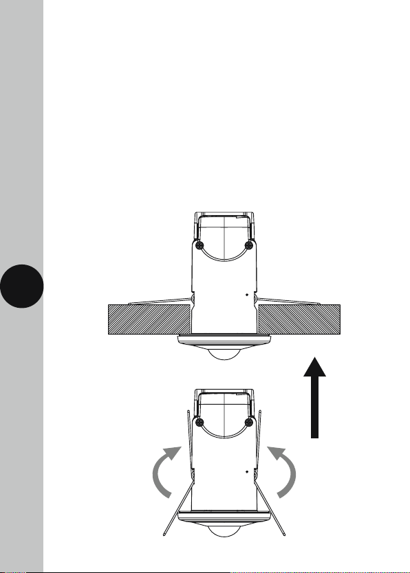
5.11 Push back the locating springs and feed the unit into the ceiling
void via the 45mm hole. The locating springs will now fold back
and hold the PDFM360MINI sensor in place.
3 4
Page 5

230V AC 50Hz
MAINS SUPPLY
L
N
6. Connection Diagram
• Connect the 230V 50Hz main supply and load cables to the terminal block
as follows;
DETECTOR
L
N
4
LOAD
230V 50Hz Mains Supply
Live Supply (Brown or Red) to L
Neutral Supply (Blue or Black) to N
Load
Switch Live (Brown or Red) to
Neutral Load (Blue or Black) to N
ISOLATION SWITCH
Page 6

7. Setting Up
Walk Test Procedure (Test Mode)
• Turn the power to the unit ON. The lamp will immediately illuminate as the
unit goes through its “warm-up” period. After approximately 1 minute
the lamp will extinguish. This indicates the unit is wired correctly
and the unit is in ‘Test Mode’.
• Try to remain outside the detection area during the warm-up period.
• The unit will now operate during daytime as well as at night, illuminating
the lamp for approx. 3 seconds each time. This allows testing to be carried
out to establish whether the PIR sensor is covering the required area.
• Walk around the PIR sensor to establish the detection area.
• The PIR sensor will detect within an approximately 6 metre diameter circle
from the centre of the PIR sensor location with a 2.5m ceiling.
• As you cross a detection “zone” the lamp will illuminate. Now stand still
until the lamp extinguishes (this should take approx. 3 seconds).
• Start moving again after 2 seconds. Each time you cross the detection “zone”
5 6
the lamp will illuminate.
• Repeat the above, walking at various distances and angles to the unit.
This will help you to confirm the detection pattern.
Page 7

6
Setting Up for Automatic Operation (Auto Mode)
• When walk tests are complete, the unit can be adjusted for automatic operation.
• The TIME setting controls how long the unit remains illuminated following
activation and after all motion ceases.
• The time can be set variably from ‘Pulse’
10 min and 30 min.
• The PIR sensor will start counting down from the last detected movement
• While there is still movement in the detecting area, the LED indicator will flash
once and lighting will remain on and the timer will keep resetting.
• Adjust the time to the desired setting.
, 30 sec, 1 min, 5 min,
Page 8

• The PULSE setting can be used by setting the TIME adjuster to the ‘Pulse’
symbol .
• When set to pulse mode the PIR sensor will react to any motion in the
detecting area, and to the settings of Lux.
• As sensor is activated, the LED indicator and lighting will turn on for 1 second,
and off for 9 seconds, before it can be activated again.
• The LUX setting determines the level of darkness required for the unit
to start operating. The setting is best achieved by the procedure below;
1. Turn the lux control knob clockwise to set to the Sun symbol.
2. When the ambient light level reaches the level of darkness at which you wish
the lamp to become operative (i.e. at dusk) SLOWLY rotate the control in an
anti-clockwise direction until a point is reached where the lamp illuminates.
3. Leave the control set at this point.
• At this position the unit should become operative at approximately the same
level of darkness each evening.
• Observe the operation of the unit. If the unit is starting to operate too early
7 8
(i.e. when it is quite light) adjust the control slightly anti-clockwise.
If the unit starts to operate too late (i.e. when it is very dark).
Adjust the control slightly clockwise.
• Continue to adjust until the unit operates as desired.
Page 9

8
• The LUX Memory can be used by setting the Lux level to the ‘eye’ symbol .
• If the arrow is pointing to the ‘LUX Memory’ setting, the PIR sensor will take
about 5 seconds to memorize the ambient light level, from 5 lux to 200 lux
as an ON/OFF threshold.
• Re-position the shroud cover over the PIR, and turn clockwise by half a turn
until it clicks into place.
8. Lens Mask
• There is 1x lens mask included in the accessory pack.
• The purpose of the lens mask is to mask out areas not desired for detection.
You can restrict left or right detection, or reduce detection zone to cover
a smaller area.
• Use some pliers or a suitable tool to cut out the mask segment,
exposing the required area of detection.
• Remove the shroud cover from the PIR sensor by turning it anticlockwise
by a half turn.
• Insert the lens mask into the underside of the shroud cover and push thorough
it clicks into place.
• Re-position the shroud cover over the PIR, and turn clockwise by half a turn
until it clicks to secure into place.
Page 10

9
3 Year Guarantee
In the unlikely event of this product becoming faulty due to defective material or
manufacture within 3 years of the date of purchase, please return it to your supplier
in the first year with proof of purchase and it will be replaced free of charge.
For years 2 and 3 or any difficulty in the first year, telephone the helpline
on 020 8450 0515.
Note: A proof of purchase is required in all cases. For all eligible replacements (where
agreed by Timeguard) the customer is responsible for all shipping/postage charges
outside of the UK. All shipping costs are to be paid in advance before a replacement
is sent.
Page 11

10
Page 12

If you experience problems, do not immediately return the unit
to the store. Telephone the Timeguard Customer Helpline;
HELPLINE
020 8450 0515
or email helpline@timeguard.com
Qualified Customer Support Co-ordinators will be on-line
to assist in resolving your query.
For a product brochure please contact:
Timeguard Limited.
Victory Park, 400 Edgware Road,
London NW2 6ND
Sales Office: 020 8452 1112
or email csc@timeguard.com
Zerofour – May 2017
www.timeguard.com
67-058-578 (Issue 1)
 Loading...