

Page 1

Wi-Fi Controlled Time Switch
Model: NTTW IFI
Installation & Operating Instructions
Page 2

1. General Information
These instructions should be read carefully, in full, before installation.
Please note that all instructions are to be left with the customer
after installation.
Note: Timeguard reserve the right to alter these instructions,
and the SupplyMaster app, at any time.
Up to date instructions will always be available for
download at www.Timeguard.com.
2. Safety
• Before installation or maintenance, ensure the mains supply to the
time switch is switched off and the circuit supply fuses are removed
or the circuit breaker turned off.
• It is recommended that a qualified electrician is consulted or used
1 2
for the installation of this time switch and install in accordance with
the current IEE wiring and Building Regulations.
• Check that the total load on the circuit including when this time
switch is fitted does not exceed the rating of the circuit cable,
fuse or circuit breaker.
Page 3

3. Technical Specifications
• 230V AC 50 Hz
• This time switch is of class I construction and must be earthed
• Switch Rating: 16A Resistive (3.68kW) Immersion Heaters
1kW Incandescent and Halogen lighting
500W Fluorescent lighting
100W Compact fluorescent
and LED lighting
• Contact Type: Normally Open, micro disconnection
• Wi-fi specification: 2.4GHz b/g/n
• Frequency Range: 2.412 – 2.484 GHz
• Operating Modes: Permanent ON or OFF, Auto timed, Holiday
• Boost Times: 1 or 2 hour
2 3
• Output Light: Yes
• Operating Temperature: 0°C to +40°C
• IP Rating: Intended for indoor use only
• CE compliant
• Dimensions (H x W x D): 120 x 74 x 42mm
Note: Not suitable for use with Discharge Lighting.
Page 4
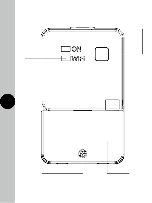
Wi-Fi
connection
indicator
ON/OFF
indicator
Override
button
and Wi-Fi
connect
3 4
Terminal
cover fixing
screw
Note: The timeswitch comes with a tamper proof cover
which is padlockable.
Terminal
cover
Page 5
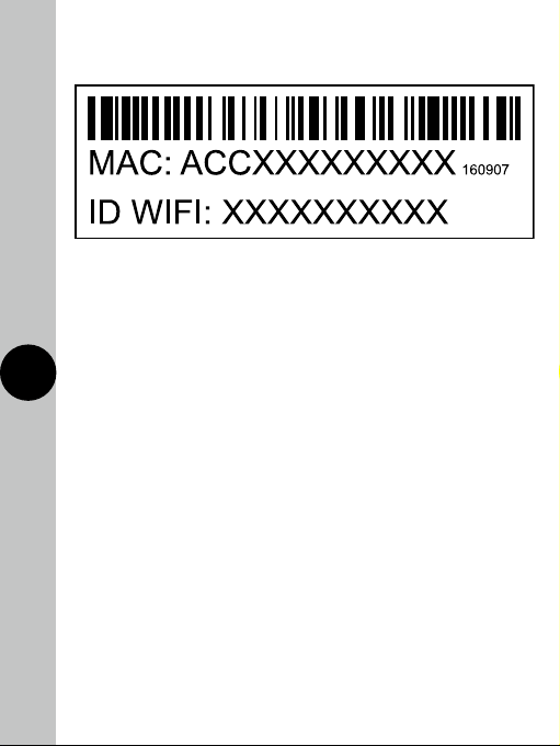
NTTWIFI MAC address and ID Wi-Fi number label
Important: Do not remove this label from the side of the product.
4. Contents
• 1x NTTWIFI time switch
• 2x Mounting screws
• 2x Cable clamp set
4 5
• 1x Plastic insert
• 1x Tamper-proof cover
• 1x Instruction manual
Note: all instructions are to be left with the customer after installation.
5. Installation
The NTTWIFI is a Wi-Fi controlled time switch which surface mounts.
There is provision for two front cables, with built in cable clamps.
The contacts are not volt free. There is a loop terminal for earth continuity.
5.1 Ensure the mains supply is switched off and the circuit supply
fuses are removed or the circuit breaker turned off.
5.2 Remove the terminal cover by undoing the fixing screw
on the bottom of the time switch.
Page 6

5.3 Mark the position of the top wall mounting screw. Drill out the
top mounting hole taking care to avoid any joists, electrical cables
or water/gas pipes that may be hidden beneath the surface.
Insert the rawl plug into the hole.
5.4 Fix the top mounting screw and leave 2.5mm proud off of the wall.
5.5 Place the key hole in the top of the product, over the screw head,
and slide down.
5.6 Mark the position of the lower mounting hole on the wall using
the wall plate as a template.
5.7 Remove the product and drill out the lower mounting hole again
taking care to avoid any joists, electrical cables or water/gas pipes
that may be hidden beneath the surface. Insert the rawl plug into
the hole.
5.8 The 230V 50Hz supply and load cables can enter through the
5 6
rear knock outs or the front cable entry ports provided. If the rear
knock outs are being used, remove the blanking plates and pass
the supply and load cables through the holes.
5.9 Place the key hole in the top of the product again, over the screw
head, and slide down.
5.10 Secure the unit to the wall using the lower mounting screw.
If the wiring is through the front cable entry ports, use the cable
clamps provided to secure the supply and load cables.
5.11 Terminate the supply and load cables to the terminal block
ensuring correct polarity is observed and that all bare conductors
are sleeved. Please note the connections are marked beneath
the terminal block (see section 6. Connections).
5.12 Secure the terminal cover back into place using the fixing screw.
Page 7

6. Connections
• The terminals are marked as follows;
6 7
Live Supply
Terminal
(Brown or
Red) 230V
50Hz
Neutral
Supply
Terminal
(Blue or
Black)
Neutral
Load
Terminal
(Blue or
Black)
Switched
Live Load
Terminal
(Brown or
Red)
Loop
terminal
for earth
continuity
Green/
Yellow
Page 8

7. Setup
Note: the mobile or tablet device must be connected to a 2.4 GHz band
on the router. Pairing on the 5GHz band will result with paring either
timing out or being unsuccessful. Refer to your ISP (Internet Service
Provider) on separating the bands if required.
7.1 Ensure your phone or tablet is connected to your local
Wi-Fi network.
7.2 Download the Timeguard Supplymaster App onto your phone
or tablet by searching for Timeguard on Google Play store or
the Apple App store.
7 8
Page 9

7.3 Install the App, and open it to the registration page.
7.4 Users must first register, and then log in to use App.
First time users must use the main account log in.
Note: User names and passwords cannot contain any
spaces or special characters, and must use letters and
numbers only.
7.5 Then, press the + button (bottom right on the phones screen
to open the add devices menu.
7.6 The Wi-Fi network the mobile or tablet is connected to will be
shown on the App, enter the password for the network SSID.
Important – DO NOT PRESS START AS OF YET.
7.7 On the NTTWIFI, hold down the override button, until the blue
LED light starts to flash.
7.8 Once the blue LED is flashing press start in the App.
8 9
The App will search for an available device.
7.9 Once the App has found and configured the NTTWIFI to the
network. the App will prompt the user to rename the device.
If this fails to happen the device name can be manually changed
at any time. From the devices menu swipe left on the device that
requires renaming, then press press edit. An editable name field
called ‘Name:’ will be shown under device information, tap the
field to rename the device. When the name has been changed
confirm this action by pressing the tick icon.
Note: If the device is to be sold, it must be deleted from
the App by the Main account holder. The device can only
be registered to one account at a time.
Page 10

8. Features of the NTTWIFI Device
Micro Disconnection
• The unit offers micro disconnection of the load using the
programmed times.
• Micro disconnection can also be applied using the override switch
on the front of the unit.
Manual Override
• The override button on the front of the unit provides a permanent off,
or on, until the button is pressed again. It is not overridden by the
next program from the App.
• During the overridden period, the App will show permanent ON, or
permanent OFF. The override can be cancelled in the App by putting
the mode back to Auto Timed.
Light Indicators
9 10
• Red ON/OFF indicator. The red light will turn ON when there is
output, and will turn OFF when there is no output. The red light
will flash if there is output, but there is no output load detected.
• Blue Wi-Fi connection indicator. This will illuminate when the
device is connected to Wi-Fi, as detailed in section 7. Setup.
This indicator will flash slowly when attempting to connect to
the server.
Page 11

9. Features of the Android
and IOS App
General
• The App can be accessed, and the device controlled from any
accessible Wi-Fi zone. Once Wi-Fi is set up on the device, the App
can also control the NTT through 4g. The NTT must be connected
to a Wi-Fi network.
• The App can be downloaded from the Google play store
or Apple store.
• An NTTWIFI can be used to provide convenient, easy programming,
from your phone or tablet. Program changes can be made at any
time, from any location, which will enable the user to save money by
cancelling programmed times during periods of unexpected absence.
• There are useful programming tips and help available on the
10
Timeguard YouTube channel. You can access the link directly from
our website www.Timeguard.com or go to the YouTube home page
and search ‘Timeguard’.
Page 12

Device Home Screen
• From log in, the user is presented with a list of devices.
Each of these has a device home screen.
When a device is selected, the home screen is then shown.
Device name
11
Back
button
Time of next
programme
change
Advance
button
Programme
entry
Settings
Mode
indicator
Output
indicator
Boost
Button
Page 13

Operating Modes
• The following options are available in Settings
Auto: Controlled by the timer programme, and can be temporarily
overridden by Boost or Advance.
Permanent OFF: Output is off until auto is re enabled by the user.
In this mode, boost and advance are disabled.
Permanent ON: Output is on until auto is re enabled by the user.
In this mode, boost and advance are disabled.
Holiday: Output is off until the date entered by the user, at which
time ON/OFF times will default back to the entered program.
• Only one mode can be selected at any time. Permanent OFF, ON,
and holiday can be cancelled by returning the App to Auto mode.
12
Boost
• From OFF, a one or two hour boost can be set using the
boost button. A third press of boost will cancel.
• The duration of the boost is shown on the device home screen,
and this will count down the time to the end of the boost period.
• From ON, a one or two hour boost time is added to the programmed
end time. This is shown on the device home screen.
Note: Boost will not cross midnight.
:
Page 14

Advance
• Advance changes the output state until the next
programmed change.
Note: The display will show the next program change:
• The time of the next programmed change is shown on the device
home screen. It also shows the boost time in boost mode (see above).
13 14
Program Entry
• The app supports multiple programmed times, with an easy repeat
function for different days. Up to 6 times can be added if required
(using the plus key), or deleted.
• Time entry is programmed via the program key on the device home page.
Hold the chosen time down to edit the times, hold the day MTWTFSaSu
to change repeats, or hold the left side of time box to delete.
• The default times are 06:00 to 08:00, and 18:00 to 20:00 every day.
• Times can be programmed across midnight. Enter a start and end
time before midnight. Enter a second set of times after midnight.
Turn off the first end time, and the second start time using the
green sliders. Set the repeats.
Page 15

Alternative Program Periods
• The App supports multiple alternative programs. This is useful for
keeping separate sets of programs, for use in school holidays, periods
of non-residency, pre and post summer time, seasonal programs,
and periods of unexpected residency such as illness. This means that
the original time programs can be saved, and reverted back to when
needed, without the need for re-programming.
• Hold the program name to edit or delete, and use the plus key
to add new programs.
12/24 Hour Clock
• Times can be shown in either 12 or 24 hour style, in Advanced Settings.
Clear ON/OFF Status
• The device home screen clearly shows output status through both
14 15
text (ON/OFF), and colour change of advance button (Red OFF,
Green ON).Settings.
Supports Multiple Users
• Additional users can be added by the Main Account holder,
in Advanced Settings, to allow sub account users to control the
NTT device. This is useful for student accommodation, families,
rented properties and similar.
• Users can be both added and deleted by the Main account
holder only. All other features of the App are the same. Users are
deleted by swiping their name to the left, in Edit/remove user.
Users can be edited in the same way, which enables User names,
passwords, and email addresses to be updated.
• The user has to log in as a Main account or a Sub account.
There can only be one main account.
Page 16

Positive Affirmation of ON/OFF Status
• With output status not enabled (default), the advance button shows
red OFF, green ON.
• Output status will not work unless there is more than a 10W load
present. There will still be an output, but this will not show on the
device home screen. At loads below 10W, the advance button will
remain red, but show the word ON to show that it is a programmed
ON period, but the device cannot detect a load.
• Output status shows that the device is working, and will only show
a change of state if there has definitely been a change of output
state (above 10W).
• With output status enabled, the advance button will show what is
happening with the output. There is an icon
which shows that this feature has been enabled.
15 16
• If there is no load detected during an on period, the advance
button will show red, ON. This is a fault condition, as the output
is not detected.
• Once the output has been detected, the advance button
shows green, ON.
• If there has been a load measured at some point in the ON period,
but the output can no longer be detected, the indicator will show
orange (stand by), until the load is detected again, when it will
show green. This is common when the output has a secondary
control, such as a thermostat.
on the home screen
Page 17

Supports Multiple Devices
• Additional NTT devices can be added if required, and controlled
in the same App. Common programming of separate devices is not
possible, each must be programmed individually. Devices can be
deleted if no longer required, using Remove Device in Advanced
Settings, choose device to be removed, and swipe left.
App Download
• This shows the version number of the App, and will notify
if an update is available.
User Manual
• This is a link to the Timeguard web page version of these instructions.
There is also a link to a Youtube site, where there are videos of the
App functions.
http://www.timeguard.com/pdf-instructions
16 17
https://www.youtube.com/timeguardlimited
Privacy Statement
• There is a link to the Timeguard privacy statement in Advanced settings.
This details what data will be stored by Timeguard, and how it will
be used.
• The privacy statement is available at;
http://www.timeguard.com/privacy-policy
About
• This gives the contact details of Timeguard Ltd.
Page 18

Graphical Representation of the Last 24 Hours
• With output status enabled, there is a graphical representation
that compares programmed on times with actual output. This can
be used to check that the NTT (and the connected appliance)
has been working correctly.
• For appliances with additional controls (for instance thermostats),
the output load is not consistently on during the programmed on
period. The graphical representation will show this difference.
Pink bars represent when there was an output, grey represents
the programmed times.
Historical Summary
• There is a brief summary of the last ON period, showing the duration
of the period, and the length of time there was an output.
Time Zones
17 18
• This unit is designed to be used in the UK so will come pre-set
to UK time. This cannot be altered.
Page 19

3 Year Guarantee
In the unlikely event of this product becoming faulty due to defective
material or manufacture, within 3 years of the date of purchase, please
return it to your supplier in the first year with proof of purchase and it will
be replaced free of charge. For years 2 to 3 or any difficulty in the
first year, telephone our helpline.
Note: a proof of purchase is required in all cases. For all eligible
replacements (where agreed by Timeguard) the customer is responsible
for all shipping/postage charges outside of the UK. All shipping costs
are to be paid in advance before a replacement is sent.
18
Page 20

If you experience problems, do not
immediately return the unit to the store.
Telephone the Timeguard Customer Helpline;
HELPLINE
020 8450 0515
or email
helpline@timeguard.com
Qualified Customer Support Co-ordinators
will be on-line to assist in resolving
your query.
For a product brochure please contact:
Timeguard Limited.
Victory Park, 400 Edgware Road,
London NW2 6ND
Sales Office: 020 8452 1112
or email csc@timeguard.com
www.timeguard.com
67.058.618 (Issue 1)
Zerofour – April 2018
 Loading...