

Page 1
Installation & Operating Instructions
Timer Modules
MEU11 – 24 Hour Module,
MEU17 – 7 Day Module
(Without Housing)
EMU11 – 24 Hour Module,
EMU17 – 7 Day Module
(With Housing – Giving panel mounting facility)
Page 2

1
1. General Information
These instructions should be read carefully
and retained for further reference and maintenance.
2. Safety
• Before installation or maintenance, ensure the
3V DC supply to the timer module is switched off.
• It is recommended that a qualified electrician is
consulted or used for the installation of this timer
module and install in accordance with the current
IEE wiring and Building Regulations.
• Check that the total load on the circuit before
attempting to use the time module for your
OEM application.
3. Technical Specifications
General
• Requires an external diode, resistor and relay
to switch mains voltage.
• Manual Override – ON/OFF until next programme.
• Operating Temperature – 0°C to +55°C.
• Power Reserve – Non replaceable rechargeable
factory fitted battery, Metal Hydride, 1000 hours.
• CE Compliant.
Page 3
2
MEU11 & EMU11 24 Hour Modules
• 24 Hour Time Period – 4 ON/OFF programmes.
MEU17 & MEU17 7 Day Modules
• 7 Day Time Period – 6 ON/OFF programmes,
daily, weekly, weekend or weekday options.
4. Contents
• 1x Timer module.
• 1x Panel mount bezel.
• 1x Tamper proof cover.
• 4x Surface mount stand offs (length 10mm).
• 2x Panel mount bolts.
• 2x Self-tapping screws (No. 4 x 5/8in)
for panel mount bolts.
• 2x Self-tapping screws (No. 6 x 3/8in)
for attaching bezel to EMU11.
5. Installation
Page 4
3
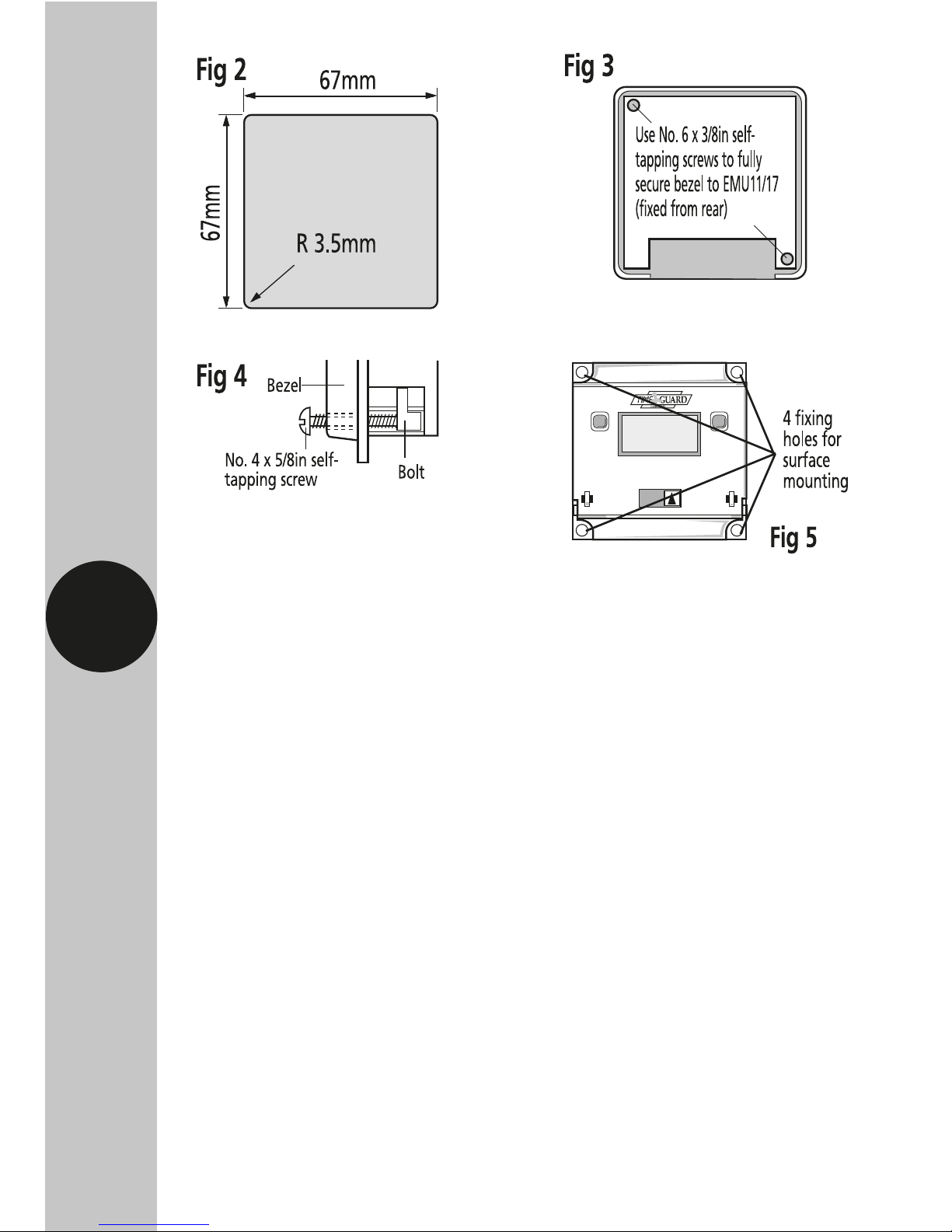
Panel Mounting
• For panel mounting (in panels up to 7.0mm
thick with the cut-out as shown in figure 2)
the EMU11/17 should be snapped into the bezel
supplied and secured in place by the use of the
2x No. 6 x 3/8 in self-tapping screws provided
(as shown in figure 3).
• When selecting a position for the unit, bear in
mind that a clearance behind the front panel
surface of 26.0mm is required over the full
area of the panel cut-out.
• The unit is designed to be mounted from the
front of the panel by the following procedure;
Page 5

4
5.1 Insert the 2 bolts provided in the locations as
shown in figure 4.
5.2 Then insert the 2x No.4 x 5/8 in self-tapping
screws into the bolts and engage thread.
5.3 Make connections to the unit by wires
terminated in a Molex 4 way 7720 or similar
connector from behind the panel.
5.4 Insert the EMU11/17 complete with bezel into
the panel and tighten up the 2x No.4 selftapping screws. The ears on the bolts will rotate
as you tighten to clamp the unit to the panel.
Surface Mounting
• The EMU11/17 without bezel can be surface
mounted using the 4 securing holes as shown
in figure 5.
• The unit can be stood off from the mounting
surface by 10mm using the 4 spacers if required.
• Screws are not provided and it must be
remembered that if used in this way the
EMU11/17 must be installed within a housing
or cubicle to prevent access to the mains
terminations.
Page 6

5
6. Connection (All models)
Single Resistor PSU (MEU11 & MEU17 only)
Two Resistor PSU – gives Optimum
EMC Performance (MEU11 & MEU17 only)
Page 7

6
All Types Connections
Pin 1: Common.
Pin 2: Positive battery charge plus relay current.
Min 0.50 mA (No relay).
Pin 3: Relay connection.
Pin 4: Output & relay connection. NPN open
connector. Max 10 mA, 47 V A Molex 7720
4 way connector or similar is recommended.
MEU11 and MEU17 – Typical Usage
The examples in figs 6, 7 and 8 show the module
driving a Shrack 48V relay with power derived
from the mains. Type RP330048 or RP331048
(Changeover contracts). In these configurations the
relay pulls in at 47V and is held at above 24V with
mains voltages down to 200V.
EMU11 and EMU17 – Typical Usage
In this case the circuit in fig 6 can be used with a
10K, 3W resistor in place of the 15K, 2W resistor
shown and a 1.3W zener must be connected
between pins 1 and 2 of the module. The circuit
in fig 7 can be used with two 5K1, 1.5W resistors in
place of the 7K5, 1W resistors shown and a 1.3W
zener must be connected between pins 1 and 2
Page 8

7
of the module. The circuit in fig 8 can be used
with a 330nF, X 250V AC capacitor instead of the
220nf capacitor shown and a 1.3W zener must be
connected between pins 1 and 2 of the module.
In all cases the zener is 47V and its cathode is
connected to module pin 2.
Capacitor PSU (MEU11 & MEU17 only)
Page 9

8
7. Programming Instructions
Easy view 24 hour
digital clock/timer
display
Easy view 24 hour
digital clock/timer
display
Day indicator
1 = Monday
7 = Sunday
Programme
Button used
to select the
clock time and
the 4 ON/OFF
programme
times and to
review them
once set
Output Status
showing unit either
ON or OFF
Output Status
showing unit either
ON or OFF
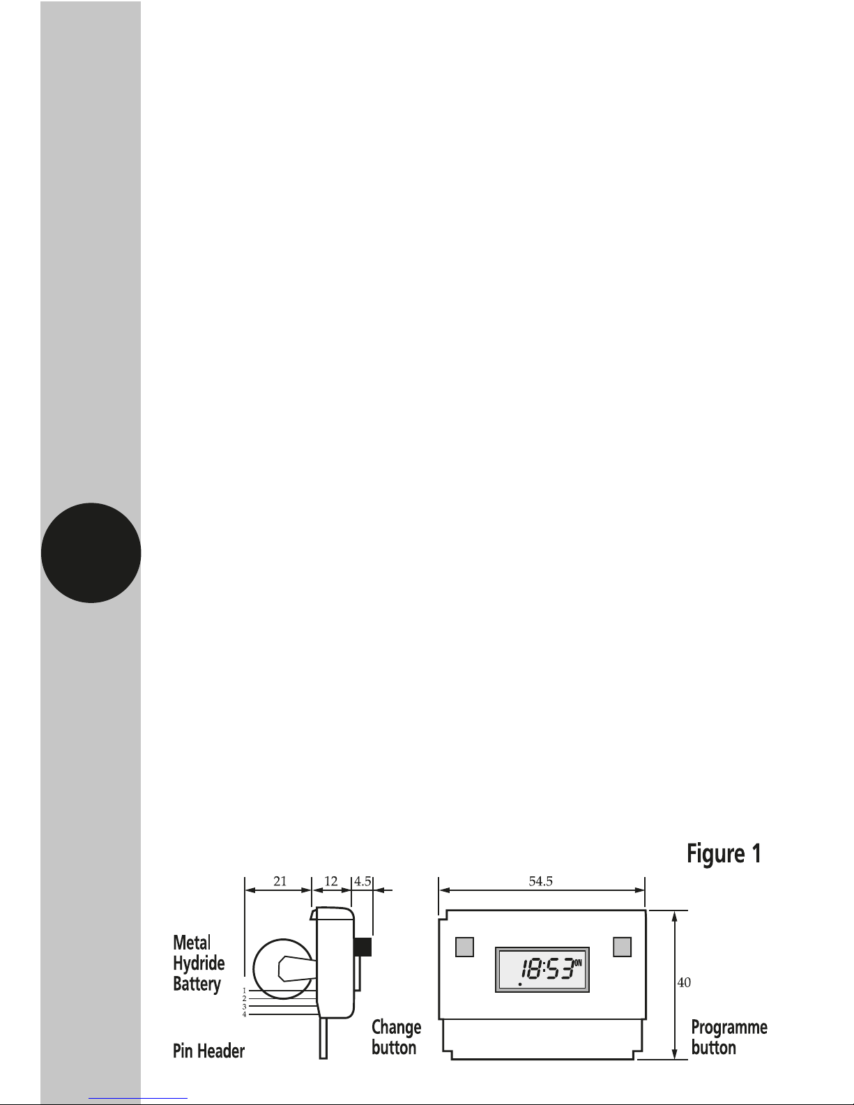
Change
Button
sets Hours
and Minute
times and
self cancelling
override
Change
Button
sets Hours
and Minute
times and
self cancelling
override
Programme
Button used
to select the
clock time
and the
6 ON/OFF
programme
times and to
review them
once set
24 Hour Model
7 Day Model
Page 10
5
7.1 Programming Overview
To enter the programming mode, press and hold the
‘Program’ button for 2 to 3 seconds and then release
the button. Only two setting buttons are required
during the programming process. The ‘Change’ button
is used to set the hours and minutes, the ‘Program’
button is used to move to the next stage of the
programming process. Each time the ‘Program’ button
is pressed the display will flash either the hours or the
minutes in turn, starting with the clock then the first
ON time, first OFF time, second ON time and so on.
Note: Button pauses greater than 1 minute
during programming will result in an
automatic return to operating mode.
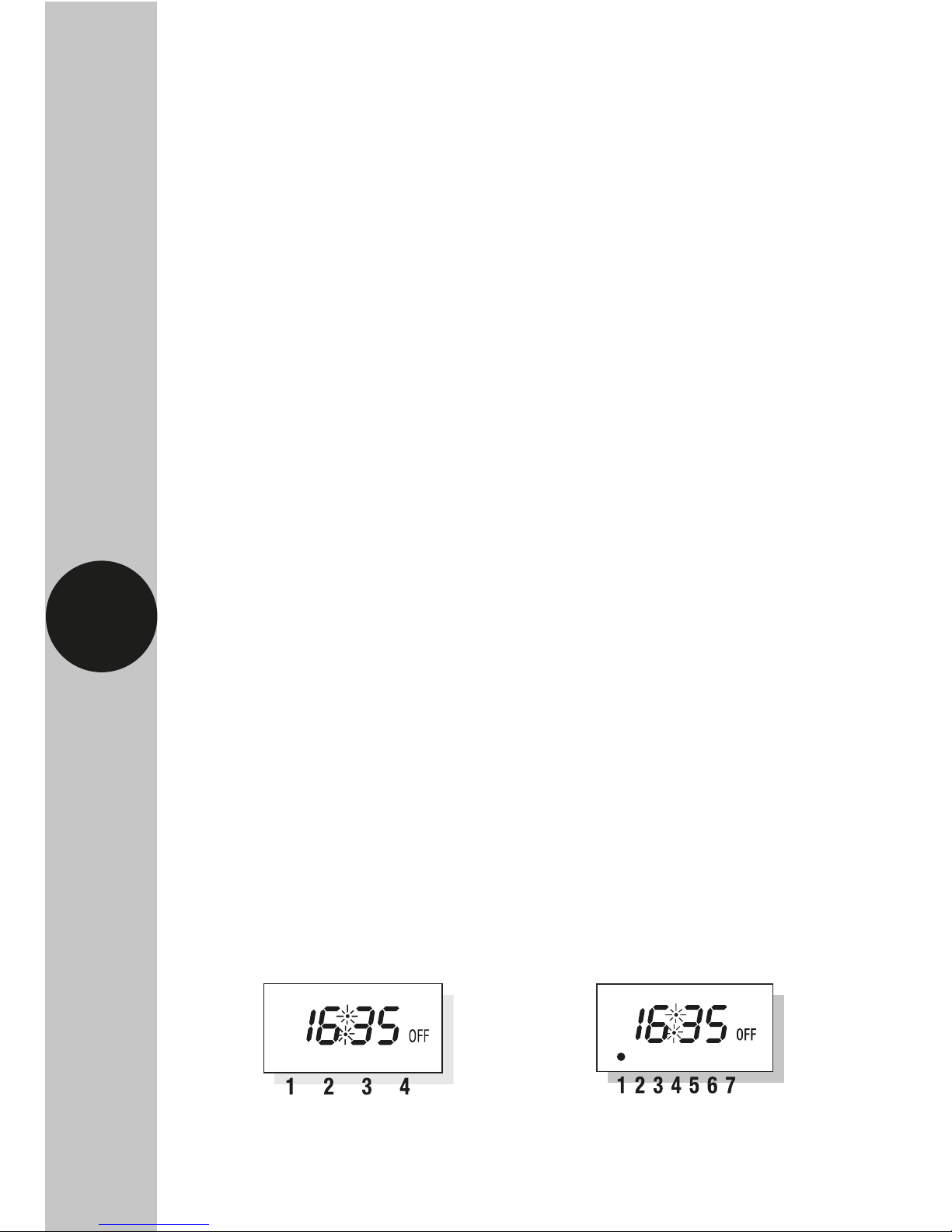
7.2 Normal Operating Mode
In normal operation the unit will display the correct
time with the colon flashing. The output status will
be shown by either ON or OFF on the display.
24 Hour Version 7 Day Version
Page 11

6
7.3 Setting Clock & Programming
After Reset
• To clear the memory and reset the unit press hold
down the ‘Change’ and ‘Program’ button until the
display goes blank.
• Release both of the buttons. After a few
seconds the display will show the clock with
the hour digit blinking.
• For the 7 day version there will be a dot flashing
over number 1 which is Monday and 7 being
Sunday. Press the ‘Change’ button to select your
current day. Once this is complete press the
‘Program’ button to move to setting the clock.
You are now in the clock setting mode at
the beginning of the programme sequence
• To set the hour for the clock press the
‘Change’
button to advance the hour setting. For a rapid
change of the hour setting hold down the
‘Change’
button and release when the correct hour value
is selected.
• Press the ‘Program’ button once and the minutes
will flash, press the ‘Change’ button to advance
the minutes setting to the correct value required.
Again you may hold down the ‘Change’ button for
a rapid change of the minutes if you wish to do so.
Page 12

7
7.4 Programme 1 ON time (7 Day
Models Only EMU17 & MEU17)
(For EMU11 & MEU11 follow from the
next bullet point, programmes will run
on a daily Basis)
Press the ‘Change’ button to select the appropriate
group you require your programme to run for; you
can also set individual days.
• Press the ‘Change’ button to select the hour you
require for the programme.
• Press the ‘Program’ button to confirm the hour
and advance to the minute setting.
• Press the ‘Program’ button once, the clock is now
set and you are ready to enter the first ON time.
You will now find the hour digits flashing
if you own the 24 hour models and if you
own the 7 day models you will see
the first five dots flashing which
represents Monday to Friday.
Page 13

8
• Press the ‘Change’ button to select the minutes
you require for the programme.
• Press the ‘Program’ button to confirm the
minutes for the ON time and move on to setting
programme 2 ON.
• Repeat the steps from section 7.4 ‘Programme 1
ON time’ for additional programmes if required.
Note: The 24 hour models have 4 programme
memory slots, and the 7 day models have
6 programme memory slots.
• If you wish to exit the program mode at anytime,
press and hold the ‘Program’ button until you
are back at the current time.
• IMPORTANT: Once programming has been
completed, the unit will show an OFF status by
default. If you require power output now, press
the ‘CHANGE’ button once. This will override the
unit until the next programmed OFF time.
If you do not do this, the unit will simply turn ON
at the next scheduled ON time (even if this is the
following day).
7.5 Program Review
When in operating mode press the ‘Program’ button
for 3 seconds and the clock symbol, hours and
minute’s symbol on the display will flash, this is
Page 14

9
review mode. If any changes are required to the
current set programmes press the ‘Change’ button
to start programming mode and then follow steps
from ‘Programme 1 ON time’.
7.6 Cancelling Programmes
To clear all programmes, press and hold down
the ‘Change’ and ‘Program’ buttons until the display
goes blank. Release both buttons and after a few
seconds you will be prompted to set the clock. Once
set you can re-enter your programme times.
7.7 Clearing Programmes
Any individual programme can be cancelled
by clearing its ON and OFF time. Follow the steps
as mentioned in section 7.5 ‘Program Review’ until
you reach the program you wish to cancel. Press the
‘Change’ button until the hour digits show --: and
press the program button to clear the programme.
7.8 Self-Cancelling Override
To change the output status from ON to OFF
or vice versa during normal operation press the
‘Change’ button. If the output status is OFF, it will
change to ON until the next programmed OFF time.
If the output is ON, it will change to OFF until the
next programmed ON time.
Page 15

10
1 Year Guarantee
If you experience any problems, do not immediately
return the unit to store, please telephone our
helpline. In the unlikely event of this product
becoming faulty due to defective material or
manufacture, please return it to your supplier within
1 year along with proof of purchase and it will be
replaced free of charge.
Note: a proof of purchase is required in all cases.
For all eligible replacements (where agreed by
Timeguard) the customer is responsible for all
shipping/postage charges outside of the UK.
All shipping costs are to be paid in advance
before a replacement is sent.
8. Battery
The modules are supplied with factory fitted with
a non-replaceable, re-rechargeable, Metal Hydride
battery back-up with 1000 hours reserve.
Note: To preserve battery life, it is not recommended
that these modules remain disconnected from a
charging source for a period of more than
six months.
Page 16

67-057-97 (Issue 4)
Timeguard Limited.
Victory Park, 400 Edgware Road,
London NW2 6ND
Sales Office: 020 8452 1112
or email csc
@
timeguard.com
For a product brochure please contact:
Qualified Customer Support Co-ordinators will be on-line
to assist in resolving your query.
If you experience problems, do not immediately
return the unit to the store.
Telephone the Timeguard Customer Helpline;
HELPLINE
020 8450 0515
or email helpline
@
timeguard.com
www.timeguard.com
Zerofour – December 2016
 Loading...