

Page 1

LED FLOODLIGHT
Model: LEDX10PIR
Model: LEDX20PIR
Page 2

1. Designated Use
1
8
0
1.8 TO 2.5 METER
12 METER
3 METER
1
8
0
1.8 TO 2.5 METER
12 METER
3 METER
1
8
0
1.8 TO 2.5 METER
12 METER
3 METER
• LEDX10PIR and LEDX20PIR are an outdoor motion detector for
automatic LED lighting control.
• Mainly for wall installation.
• Simple plug in wall plate for easy & safe connection
• Suitable for a wide range of locations: corridors, gardens, staircases,
entrances, garages, outdoor parking areas etc.
WARNING
2. Basic Safety Instruction
Danger of death through electric shock.
• Must only be installed by qualifi ed electricians.
• Avoid the metal parts of the device due to potentially high temperature.
• Conforms to the latest EC directives.
1
• Designed for use in normal environments
• Intended for outdoor installation.
• Energy saving.
• Long LED lamp life time.
Index :
Page 2 Contents and Tools required
Page 3 Connection and Installation procedure
Page 4 Installation procedure
Page 5 Sensor detection range
Page 6 Walk test & adjustment, Detector head adjustment
Page 7
Page 8 Lens masking
Page 9 Manual Override Mode, Lamp adjustment and Warning
Page 10
Setting advise and Knob settings
Technical specifications
Page 3
1
8
0
1.8 TO 2.5 METER
12 METER
3 METER
1
8
0
1.8 TO 2.5 METER
12 METER
3 METER
1
8
0
1.8 TO 2.5 METER
12 METER
3 METER
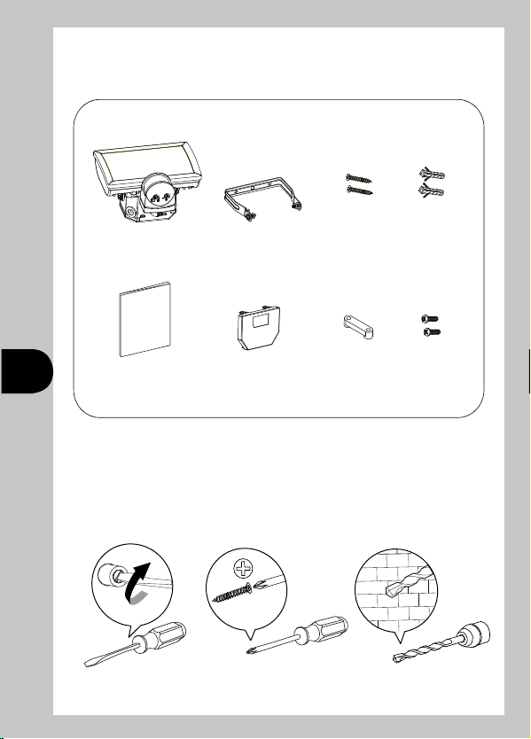
3. Contents:
What’s in the box?
Screw:
M4x32mm
X 1
INSTRUCTIONS
MANUAL
2 3
X 1
X 1
X 1
X 2 X 2
X 1 X 2
Screw peg:
6x30mm
Screw: M3x12mm
4. Tools required:
Tools / Equipment need for installation.
Flat blade screw driver Suitable for screw head Drill bit with diameter 6mm
X 1
X 1
X 1
Page 4
1
8
0
1.8 TO 2.5 METER
12 METER
3 METER
1
8
0
1.8 TO 2.5 METER
12 METER
3 METER
1
8
0
1.8 TO 2.5 METER
12 METER
3 METER
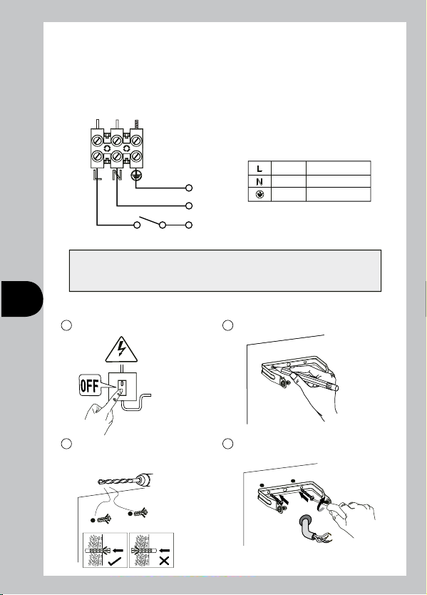
5. Connection:
Connect the cable to the terminal block as follows
(see connection diagram):
Ensure the connections are secure. Refit wall plate ensuring it clicks
firmly into place.
Mains
Supply
E
N
Isolation
L
Switch
LIVE
NEUTRAL
EARTH
BROWN
BLUE
GREEN / YELLOW
Switch off the electricity at the fuse box by removing the relevant fuse or
switching off the circuit breaker before proceeding with the installation.
6. Installation Procedure:
1
Switch off the power.
230V
3
Drill and push the screw
peg into the hole.
φ
6mm
*** IMPORTANT ***
2
Marking the screw hole.
4
Fix the U bracket to the wall.
Mounting Srews: (M4 x 32mm) x 2
Page 5

1
8
0
1.8 TO 2.5 METER
12 METER
3 METER
1
8
0
1.8 TO 2.5 METER
12 METER
3 METER
1
8
0
1.8 TO 2.5 METER
12 METER
3 METER
5
First, feed the cable through the
rubber gasket of the junction box.
6
Attach the strain relief to the
device and screw in.
4
EARTH
7
Tighten the screws.
Connect the individual wires to the appropriate terminal then tighten
9
Loosen the screws.
8
Srews: (M3 x 12mm) x 2
the screw.
CONNECTION
( See connection diagram )
Connect the mains supply
cable to the on the terminal
block backplate as follows.
NEUTRAL
EARTH
10
Attach the
wallplate
to the device.
11
Attach the device to the U
bracket then tighten the
screws on both sides.
12
Connect device
to the mains.
Unit goes into
warm-up period
for 40 sec.
Push
“Click”
LIVE
BROWN
BLUE
GREEN / YELLOW
Page 6

1
8
0
1.8 TO 2.5 METER
12 METER
3 METER
1
8
0
1.8 TO 2.5 METER
12 METER
3 METER
1
8
0
1.8 TO 2.5 METER
12 METER
3 METER
Installation Advise:
WARNING
As the detector reacts to variations in temperature, avoid situations:
• Do not direct motion detectors at objects with highly-reflective surface
such as mirrors etc.
• Do not install motion detectors near heat sources such as heating outlets,
air conditioning system, lamps etc.
• Do not direct the motion detector at objects that move in the wind such
as curtains, large plants etc.
• Take account of motion direction during test run.
5
40
30
20
10
40
40
30
20
10
40
Detection Range:
LEDX10PIR and LEDX20PIR:
Recommended installation height is 2.5 meter above
ground, the maximum detection range about 12 meter and at the angle
of about 180 deg.
up to12m
2.5 METER
3 METER
12 METER
0
8
1
40
30
20
10
40
3m
180°
180°
Page 7

Walk Test and Adjustment
The purpose of Walk Test is used to test and adjust the detection coverage of
LEDX10PIR and LEDX20PIR under auto mode.
• Adjust the Time knob to minimum (fully anti-clockwise), then conduct a
walk test as described in test procedure.
Test procedure:
• Adjust the Time knob to (fully anti-clockwise), (Lux knob can be “Sun” or
Moon”).
• Switch power on.
• Walk across the detection area, once the detector is triggered the lamp
will turn ON for 2 seconds.
Note walking direction when performing test.
Dusk Time
6
Test mode
Detector Head Adjustment
The detector head can be 90º turned left or right by hand and can be tilted
90º downward .
* Do not use the adjuster knobs to turn
the detector head.
2 sec
0
2
Sec
Pan left 90º
Pan right 90º
Tilt down 90º
Page 8

Knob Settings
LEDX10PIR or LEDX20PIR have two adjustment knobs:
Time and Lux at the bottom of the detector head.
• Adjust knobs carefully with flat blade screwdriver.
TIME knob setting
• You can set the time knob from 5 sec to about 10 min, LEDX10PIR or
LEDX20PIR will turn ON the lamp, for the time duration set after each
detected movement.
• Adjust the knob as desired.
LUX knob setting
• When setting the Lux knob at “MOON”, LEDX10PIR or LEDX20PIR will
only operate in the dark.
• When setting the Lux knob at “SUN”, LEDX10PIR or LEDX20PIR will
operate in any light level.
Adjustments
7 8
Dusk/Dawn
Test mode
Turn On time adjustmentEnvironment lux level to turn On
Time
10min5sec
0
5
sec
Dusk Setting (Time knob setting)
• When setting the Time knob to fully clock wise, the motion detector of
LEDX10PIR or LEDX20PIR won’t function.
The lamp will operate depending on the “LUX” level, ie Dusk to Dawn..
0
Min
10
Page 9

Lamp turns
ON at night.
Lamp turns ON
at day & night.
Setting Advise
WARNING
Lens masking
The purpose of the lens mask is to mask out areas not desired for detection.
Masking The Sensor Lens:
• To restrict the sensor coverage, preventing detection in unwanted areas,
mask the sensor lens using the masking label provided. The top section of
the lens covers long range detection, the bottom covers short range.
Similarly the left and right lens sections cover the left and right detection
areas respectively.
Page 10

Manual Override Mode:
The light can be switched on for longer time periods by use of the Manual
Override Mode.
This can be activated night by using the internal wall switch or circuit
breaker.
Switch the internal wall switch/circuit breaker single (OFF/ON) within 1.5
second.
The unit will now illuminate continuously until dawn or until switched back
into Auto Mode.
To switch the unit back into Auto Mode, switch the internal wall switch/circuit
breaker once (OFF/ON) within 1.5 second.
The unit will return to its Auto mode and will operate as set up after the walk
test procedure.
Lamp Adjustment
The lamp can be tilted upward 45º and
tilted down 60º.
9
WARNING
This product will get warm when in
normal use. Can be installed on
surfaces of normal flammability
e.g. wood, plasterboard, brickwork
and other masonry. Do not install
on flammable surfaces such as
plastics.
Tilt down 45º
60
50
40
+40
30
20
-20
10
Tilt downward 60º
Page 11

10
Technical specifications:
Energy Efficiency
Energy Usage Lamp On
Power Supply
Power Factor
Colour Temperature
Colour Rendering
Lumen Output initial
Detection Range
Detection Angle
Lamp Beam Angle
Time On Adjustment
Dusk Level Adjustment
Environmental Protection
If you experience problems refer to Troubleshooting Guide.
If problems still exist, do not immediately return the unit to store.
Telephone the Timeguard Customer Helpline
Class A+
LEDX10PIR - 10kWh/1000h, 9.5W typ
LEDX20PIR - 17kWh/1000h,16.1W typ
230 V AC ~ 50Hz
> 0.95
5000 - 5600k
> 70
LEDX10PIR - Black: 685 lm typ, White: 750 lm typ
LEDX20PIR - Black: 1260 lm typ, White: 1325 lm typ
Up to 12 metres
180º
110 x 100 degrees
The lamps are not replaceable in this product
5 seconds -10 minutes
Day & night or night only operation
IP55 (suitable for indoor and outdoor use)
020 8450 0515
Qualified Customer Support Co-ordinators will be on-line to assist
3 Year Guarantee
In the unlikely event of this product becoming faulty due
to defective material or manufacture within 3 years of the
date of purchase, please return it to your supplier in the
first year with proof of purchase and it will be replaced free
of charge. For years 2 and 3 or any difficulty in the first year telephone
the helpline on 020 8450 0515.
Note:
A proof of purchase is required in all cases. For all eligible replacements
(where agreed by Timeguard) the customer is responsible for all
shipping/postage charges outside of the UK. All shipping costs are to be
paid in advance before a replacement is sent.
in resolving your query.
Page 12

HELPLINE
020 8450 0515
or email helpline@timeguard.com
For a product brochure please contact:
Timeguard Limited.
Victory Park, 400 Edgware Road,
London NW2 6ND
Sales Offi ce: 020 8452 1112
or email csc@ timeguard.com
67.058.502
 Loading...