

Page 1
5W LED Energy Saver
PIR Bulkhead
Model: LED88PIR – Black
I n s t a l l a t i o n & Ope r a t i n g I n s t r u c t i o n s
Page 2

1. General information:
The unit utilises passive infrared technology to detec t heat radiation of mov ing human bodies.
Upon detec tion, the lamp will illuminate for a user-determined time period.
An integral daylight sensor ensures all day or night only operation.
Parts Included
• Luminaire c /w PIR Sensor unit.
• Instruc tion manual. Please keep safe
for future reference.
•
Accessory pack.
Tools & Parts Needed
• Electric or hand-held drill & bits.
• Terminal or electricians screwdriver.
• Flat and philips screwdriver.
• W ire cutter s.
2. Selecting the location:
Unit is for indoor and outdoor use. Unit must be mounted on a non-flammable surface
as a fixed luminaire, and is not suitable for portable use.
The unit can get very hot during use. Ensure the unit has cooled before handling.
1
Ensure adequate ventilation space is allowed between the unit and any o
or to either side of the unit. Suggested space is 0.5m above, 0.3m to either side & 1.0m in front.
The motion detector has a number of detection zones, at various vertical and horizont al angles
as shown (see Fig A).
A moving human body needs to cross/enter one of these zones to ac tivate the sensor. The best
all-round coverage is achieved with the unit mounted at the optimum height of 1.8m.
Careful p ositioning of the sensor will be required to ensure optimum
See diagram A detailing detection range and direction.
TOWARDS (see Fig B). T herefore position the unit so that the sensor looks ACROSS the likely
approach path.
Avoid positioning the sensor where there are any sources of heat in the detection area (extractor
fans, tumble dryer exhaust s etc.).
cause false activation under extreme conditions.
During extreme weather conditions the motion sensor may exhibit unusual behaviour. This does
not indic ate a fault with the sensor. Once normal weather conditions return, the sensor will
resume normal operation.
performance.
bject above, in front
Page 3
3. Installation:
After choosing a suitable location (see previous sec tion) install the unit as follows:
Switch off the electricity at the fuse box by removing the relevant fuse or
switc hing off the circuit breaker before proceeding with the installation.
We recommend this unit be fitted by a qualified electrician. Install in accordance with wiring and
current building regulations. Please read the instructions carefully.
The unit is suitable for connection to a 230 V AC 50Hz electricity supply. It is suggested t
the power to the unit ON & OFF. This allows the sensor to be easily switched off when not required
or for maintenance purposes.
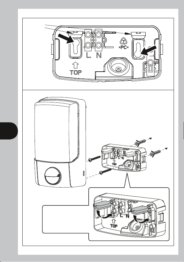
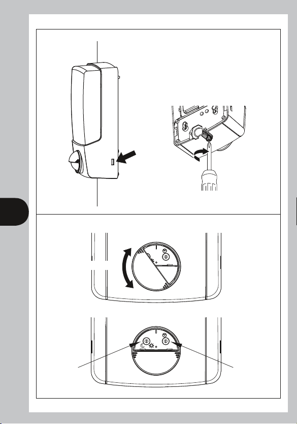
Loosen up the bottom screw (Fig C). Remove wall plate by using a small flat screwdriver (Fig C) by
gently easing the wall plate outwards.
Open the rubber plug, mark position of the fixing holes (Fig D). Drill the holes. Inser t the wall plugs
into the holes.
Pierce the grommet and pass the cable through the grommet. Clamp the cable to the rear of the
unit before securing the unit to the wall. Fit grommet into it s location hole ensuring a good seal.
Fix the unit to the wall (Fig E). Close the rubber plug after tighten the screws (Fig E). Attach the unit
2
to the wall plate by a sound of click, tighten the bottom screw (Fig F). If using a power screwdriver,
use the lowest torque setting.
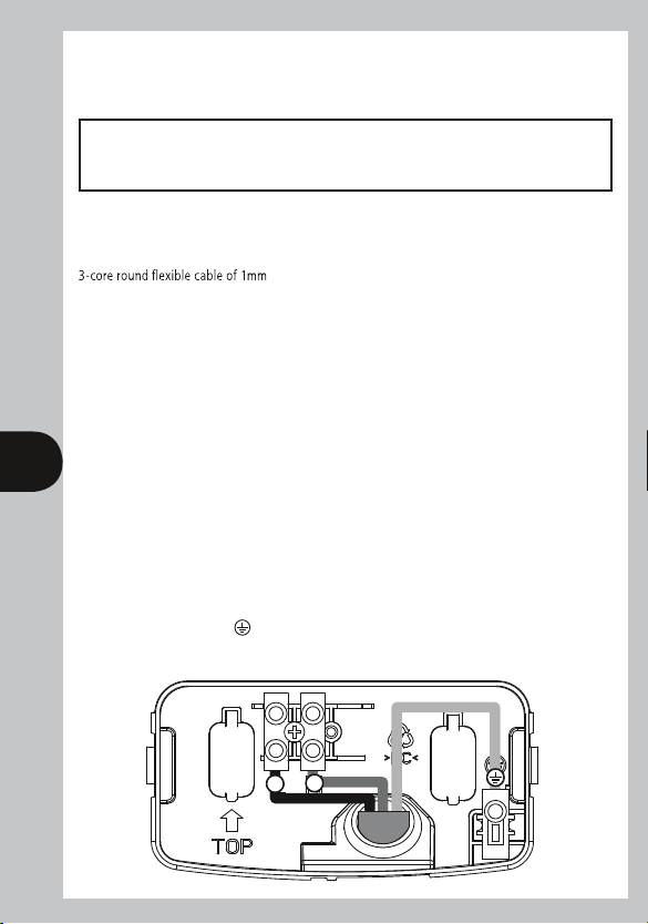
Connection
Connec t the cable to the terminal block as follows (see connection diagram):
LIVE (Brown) L
NEUTR AL (Blue) N
EARTH (Green/Yellow)
Ensure the connections are secure. Refit wall plate ensuring it clicks firmly into place.
IMPORTANT
2
gauge is used. An isolating switch should be installed to switch
hat
N
L
Page 4
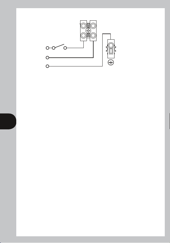
L N
Isolation
Switch
L
Mains
N
Supply
E
4. Operating and testing:
Test Mode
Rotate the sensor cover to reveal the adjustment knobs (Fig G).
The unit can be set up in daylight or at night. The adjustment k nobs are factory set. Lux is set
to the 'moon' setting and Time is set to a minimum (fully anti-clockwis e) see Fig H.
Turn the power ON. The lamp will illuminate for approximately 30 seconds.
This indicates the unit is wired correc tly.
3
After approximatel y 30 seconds the light will turn off.
The unit is now in Test Mode.
Walk Test Procedure
The lamp will now illuminate for approximately 5 seconds every time movement is detected.
Wa
lk across the detection area approximately 5 metres from the unit. Each time you are detected
the lamp will illuminate. Now stand still until the lamp extinguishes (this should take approx.
5 seconds)
Start moving again, when you are detected again the lamp will illuminate.
Repeat the above, walking at various angles and distances to the unit. This will help you to
establish the detection pattern.
Setting Up for Automatic Operation
The TIME setting controls how long the unit remains illuminated following activation and after
all motion ceases.
(See Fig H, the Time adjustment knob is indicated by the "Clock" symbol).
The minimum time (anti-clockwise) is approx. 5 seconds, whilst the maximum time (clockwise) is
approx. 10 minutes (Fig H). Set the control to the desired setting between these limits. The
DUSK control determines the level of darkness required for the unit to start operating.
Page 5

The set ting is best achieved by the procedure below:
(See Fig H, the Dusk adjustment knob is indicated by the "Moon" and "Sun" symbols).
Set the DUSK control knob fully anti clockwise. Wait until darknes s falls.
When the ambient light level reaches the level of darkness at which you w ish the lamp to become
operative (i.e.: at dusk) SLOWLY rotate the control in a clockwise direction until a point is reached
where the lamp illuminates. Leave the control set at this point.
At this position the unit sho
each evening. Obser ve the operation of the unit. If the unit is starting to operate too early
(i.e.: when it is quite bright), adjust the control slightly anti-clockwise. If the unit starts to operate
too late (i.e.: when it is very dark), adjust the control slightly clock wise.
Continue to adjust until the unit operates as desired.
uld become operative at approximately the same level of darkness
Knob Settings
Bulkhead has two adjustment knobs:
Time and Dusk at the front of the detector head which is covered by sensor cover.
• Rotate the sensor cover and adjust knobs carefully with screwdriver.
TIME knob setting
• You can set the time knob from 5 seconds to about 10 minutes, the lamp will turn On for the
4
time duration set after each detected movement.
• Adjust the knob as desired.
LUX knob setting
• When setting the Dusk knob at “MOON”, Bulkhead will only operate in the dark.
• When setting the Dusk knob at “SUN”, Bulkhead will operate in any light level.
Adjustments
D
T
D
T
TimeDusk/Dawn
H
Environment lux level to turn On
Turn On time adjustment
D
T
T
10min5sec
sec
0
5
min
0
10
D
Page 6

Dusk Setting (Time knob setting)
• When setting the Time knob to “D” (fully clockwise) (Fig I), the motion detector of Bulkhead
won’t function.
• The lamp will operate depending on the “LUX” level, ie Dusk to Dawn.
I
T
D
5. Technical specifications:
Energy Efficiency
Energy Usage
Output
Lamp Beam Angle
5
Detection Range
Detection Angle
Power Supply
Lamp Type
Time On Adjustment
Dusk Level Adjustment
Environmental Protection
EC Directives
If you experience problems refer to Troubleshooting Guide.
If problems still exist, do not immediately return the unit to store.
Telephone the Timeguard Customer Helpline
020 8450 0515
Qualified Customer Support Co-ordinators will be on-line to assist
Class A+
6kWh/1000h
310lm typical
90x90 degrees
The lamps are not replaceable in this product
Up to 7 metres
140º
230 V AC ~ 50Hz
5W LED which is the equivalent light output of a 70W
Halogen Lamp
5 seconds – 10 minutes
Day & night or night only operation
IP55 (suitable for indoor and outdoor use)
Conforms to current EC Directives
in resolving your query.
Page 7

6. Trouble shooting guide:
Problem
• Lamp stays ON all
the time at night.
• PIR keeps
activating for no
reason/at random.
• PIR sensor will not
operate at all.
6
• The PIR sensor
will not operate
at night.
• Unit activates
during the daytime
• PIR coverage is
poor/sporadic
• Detection range
varies from day
to day
Solution
The unit may be suffering from false activation. Cover the sensor
lens completely with a thick cloth. This will prevent the sensor from
"seeing" anything. If the unit now switches off after the set time
duration and does not re-activate, this indicates that the problem
was caused by false activation.
You may not be allowing the unit time to complete it's warm-up
period. Stand well out of the detection range and wait
(the warm-up period should never exceed 5 minutes).
Occasionally, winds may activate the sensor. Sometimes passages
between buildings etc. can cause a "wind tunnel" effect.
Ensure the unit is not positioned so as to allow detection of cars/
people using public thoroughfares adjacent to your property.
Check that the power is switched ON at the circuit breaker/internal
wall switch.
Turn OFF the power to the unit
as per the diagram (see previous section 3). Ensure no connections
are loose.
The level of ambient light in the area may be too bright to allow
operation at the current DUSK setting. During the hours of darkness,
adjust the DUSK control slowly clockwise until the lamp illuminates.
Refer to previous section for more details.
The level of ambient light in the area may be too dark for the
current DUSK setting. During daylight, adjust the DUSK control slightly
anti-clockwise. When the lamp turns off, enter the detection
area. If the PIR still activates, the setting is still too high. Repeat the
above procedure until the PIR does not activate when you enter the
detection area. Refer to previous section for more details.
Unit may be poorly located. See previous section –
‘Selecting The Location’ and re-locate the unit.
PIR sensors are influenced by climatic conditions. The colder the
ambient temperature, the more effective the sensor will be.
and check the wiring connections
Page 8

7
Top View
140°
Detection Angle and Range:
Min 7m range at 90˚ angle
Min 3m range at 140˚ angle
Side View
1.8m
90°
7m
Movement
A B
7m
Less
sensitive
More
sensitive
C
Page 9
8
Open rubber
plug
D
E
Close the rubber plug after
tighten the screws.
Page 10
Click
F
9
D
Rotate the sensor cover
Dusk/Dawn Time
T
D
T
G
Page 11

10
3 Year Guarantee
In the unlikely event of this product becoming faulty due to defective
material or manufacture, within 3 years of the date of purchase,
please return it to your supplier in the first year with proof of purchase
and it will be replaced free of charge. For years 2 to 3 or any difficulty
in the first year telephone our helpline on 020 8450 0515.
Note: A Proof of Purchase is required in all cases. For all eligible
replacements (where agreed by Timeguard) the customer is responsible
for all Shipping/Postage charges outside of the UK. All Shipping costs are
to be Paid in advance before a replacement is sent.
Page 12

For assistance with the product please contact:
HELPLINE
020 8450 0515
or email helpline@timeguard.com
For a product brochure please contact:
Timeguard Limited.
Victory Park, 400 Edgware Road,
London NW2 6ND
Sales Offi ce: 020 8452 1112
or email csc@timeguard.com
Zerofour – May 2013
67.058.494 (issue 1)
 Loading...