

Page 1

HELPLINE
020 8450 0515
or email helpline@timeguard.com
Knob Settings
LED400PIR has two adjustment knobs:
Time and Lux at the bottom of the detector head.
• Adjust knobs carefully with hand.
TIME knob setting
• You can set the time knob from 5 sec to about 10 min, LED400PIR will turn
On the lamp, for the time duration set after each detected movement.
• Adjust the knob as desired.
LUX knob setting
• When setting the Lux knob at “MOON”, LED400PIR will only operate in
the dark.
• When setting the Lux knob at “SUN”, LED400PIR will operate in any light level.
Adjustments
Setting Advise
WARNING
Lens masking
Lamp turns
On at night.
Lamp turns On
at day & night.
24 Hrs
Lamp adjustment
The lamp can be tilted down 55 degree and pan outward 50 degree with
the spacer or 40 degrees without.
Side View
Spacer
55°
Top View
Spacer
WARNING
High Temperature
The temperature of the lamp is very high during operation. You will get hurt
if you touch the heat sink.
40
30
20
10
40
+40
30
20
-20
10
32W LED PIR
FLOODLIGHT
Model: LED400PIRW - White
Model: LED400PIRB - Black
For a product brochure please contact:
Timeguard Limited.
Victory Park, 400 Edgware Road,
London NW2 6ND
Sales Offi ce: 020 8452 1112
or email csc@ timeguard.com
67.058.486
LED400PIRB.1 Instructs_147x105 7-11
Turn On time adjustment
7 8
0
sec
Dusk Setting (Time knob setting)
• When setting the Time knob to “D”, the motion detector of LED400PIR won’t
function.
The lamp will operate depending on the “LUX” level, ie Dusk to Dawn..
10min5sec
5
0
Min
10
Environment Lux level to turn On
The purpose of the lens mask is to mask out areas not desired for detection.
Lens mask fi tting procedure:
• Use a penknife or pliers to cut out lens mask segment, exposing area
for detection.
• Attach the lens mask to the detector head.
• Push the lens mask for it to be locked into place.
B
A
9
50°
The lamp can be tilted down 55 degree pan outward 90 degree to left
90°
The lamp can be tilted down 55 degree
and pan outward 90 degree to right.
90°
50°
55°
55°
10
TECHNICAL SPECIFICATIONS:
Supply 220 - 240V 32W
Output 2000 Lumens
Weatherproof IP55
External Up to 5 LED 400 uncontrolled lamps
Other loads
LED lamp, PF < 0.6
LED lamp, PF > 0.9
Halogen lamp load
CFL 120W Max
Fluorescent tube w/o
PF correction
50W Max
200W Max
1000W Max
200W Max
3 Year Guarantee
In the unlikely event of this product becoming faulty due
to defective material or manufacture within 3 years of the
date of purchase, please return it to your supplier in the
first year with proof of purchase and it will be replaced free
of charge. For years 2 and 3 or any difficulty in the first year telephone
the helpline on 020 8450 0515.
31-05-12 2.58pm
Page 2
1. Designated Use
• LED400PIR is an outdoor motion detector for automatic LED lighting control
• Suitable for installation on walls
• Simple plug in wall plate for easy & safe connection
• Suitable for a wide range of locations: corridors, gardens, staircases,
entrances, garages, outdoor parking areas etc.
WARNING
2. Basic Safety Instruction
Danger of death through electric shock.
• Must only be installed by qualifi ed electricians.
• Avoid the metal parts of the device due to potentially high temperature.
• The device conforms to EN60598 for designated installation; IP55 in
accordance with EN 60529 and IEC62471 Photo biological safety of
1
lamps and lamp system.
• Designed for use in normal environments
• Intended for outdoor installation.
• Energy saving.
• Long LED bulb life.
Index :
Page 2 Contents, Tools required.
Page 3 Product dimensions.
Page 4 Installation procedure.
Page 5 Sensor detection range .
Page 6 Walk test & adjustment, Detector head adjustment.
Page 7 Knob settings.
Page 8 Lens masking.
Page 9 Lamp adjustment
Page 10 High temperature in lamp.
3. Contents:
What’s in the box?
X 1
X 1
X 2
INSTRUCTION
MANUAL
X 1 X 1
X 2
2 3
4. Tools required:
Tools / Equipment need for installation.
X 1
X 1
X 1
5. Product Dimensions:
31.00
179.00
292.00
108.00
179.00
Spacer dimension:
15.00
91.00
179.00
131.00
161.00
86.00
108.00
* The Spacer is an optional fitting
which gives maximum Pan angle.
104.00
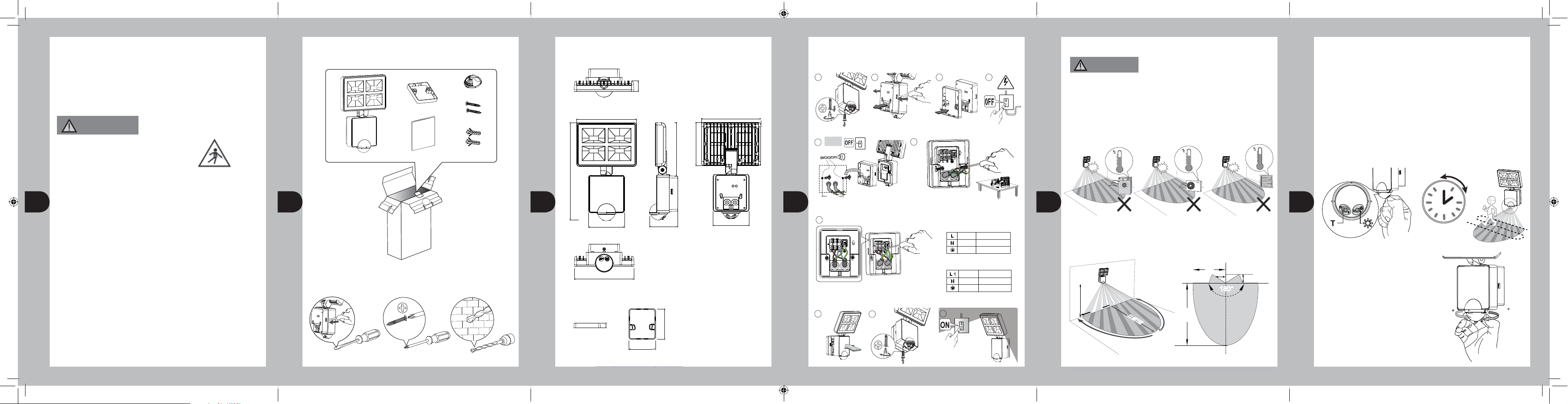
6. Installation Procedure:
Unscrew the
wall plate.
1
Fix the spacer with the wall plate to the wall or the wall plate alone.
5
CAUTION:
φ
5mm
60mm
Feed the wires through rubber gasket of the wall plate with spacer and attach to
4
corresponding terminal.
7
Attach the device
to the wall plate.
8
Push and open
the wall plate.
2
Push
6
CONNECTION:
For additional lighting, connect the external load
to the terminal box on the back plate as shown.
Screw the wall plate to the unit. Unit goes into warm-up
9
Fix the spacer
to the wall plate
- if required.
3
Use the spacer if necessary.
MOUNTING SCREW x 2
( See connection diagram )
Connect the mains supply cable to the
terminal block on the backplate as follows.
period for 40 sec.
10
LIVE
NEUTRAL
EARTH
SWITCH LIVE
NEUTRAL
EARTH
Switch off
the power.
4
240V
BROWN
BLUE
GREEN / YELLOW
BROWN
BLUE
GREEN / YELLOW
5
Installation Advise:
WARNING
As the detector responds to changes in temperature, avoid the following
situation:
• Pointing the detector towards objects with highly refl ective surfaces,
such as mirrors etc.
• Mounting the detector near heat sources, such as heating vents, air
conditioning units, lights etc.
• Pointing the detector towards objects that may move in the wind, such as
curtains, tall plants etc.
0.5m
40
30
20
10
40
40
30
20
10
40
40
30
20
10
40
Detection Range:
LED400PIR: Recommended installation height is 2.5 meter above ground, the
maximum detection range about 12 meter and at the angle of about 180 deg.
6m
1m
180°
180°
1.8 TO 2.5 M
6 METER
12 METER
12 METER
8
1
12m
0
Walk Test and Adjustment
The purpose of Walk Test is used to test and adjust the detection coverage of
LED400PIR under auto mode.
• Adjust the Time knob to “ T ”, then conduct a walk test as described in test
procedure.
Test procedure:
• Adjust the Time knob to “ T ”, (Lux knob can be “Sun” or Moon”).
• Walk across the detection area, once the detector is triggered and the lamp
will turn ON for 2 seconds.
Note walking direction when performing test.
2 sec
0
2
6
Test mode
Detector Head Adjustment
The detector head can be panned 90 deg.
to the left and 90 deg. to the right.
* Do not use the adjuster knobs to turn
the detector head.
Sec
90
90
LED400PIRB.1 Instructs_147x105 1-6
31-05-12 10.14am
Prepared by Sally
 Loading...