

Page 1
Installation & Operating Instructions
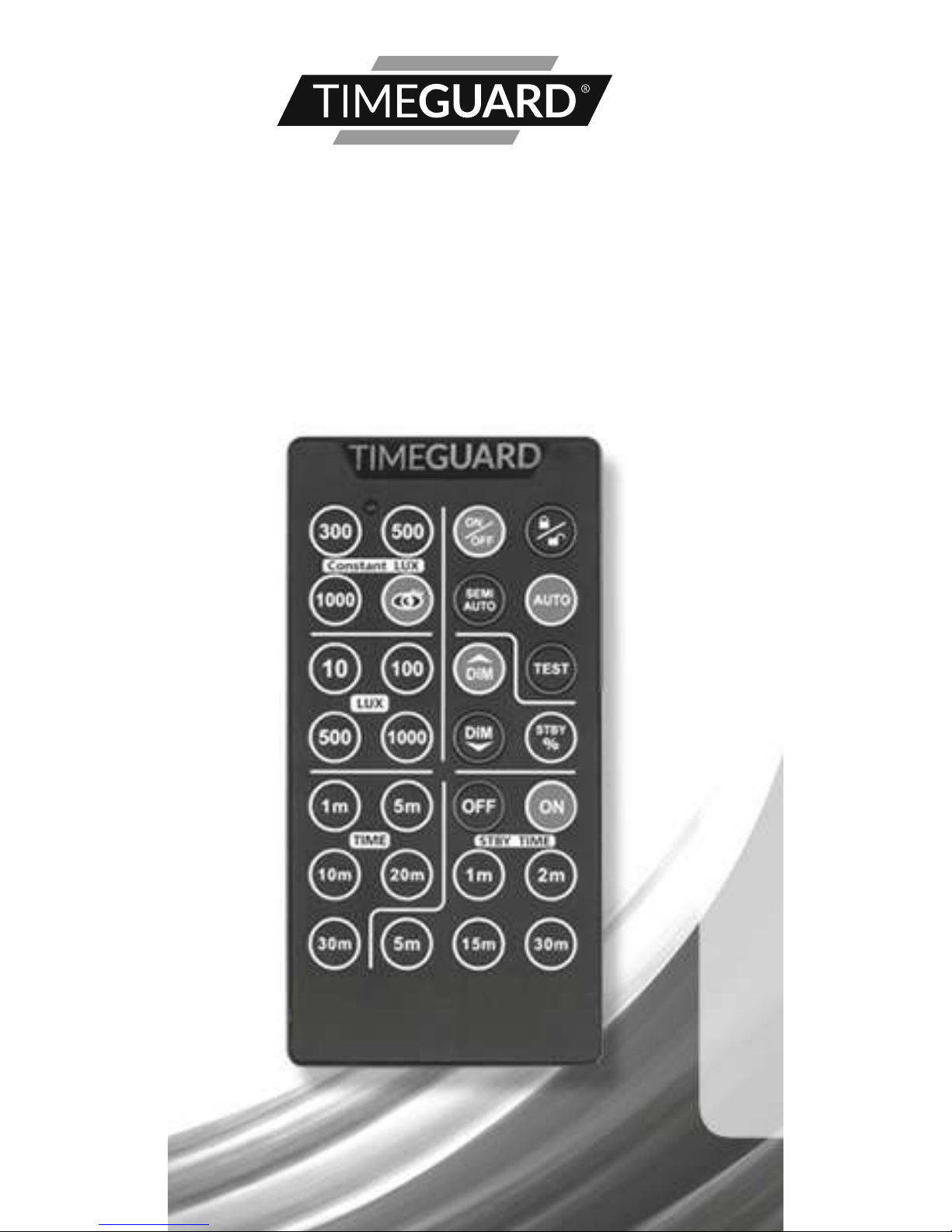
Infra-Red
DALI Remote
Control
Model: IRRDALI
Page 2

1
1. General Information
These instructions should be read
carefully and retained for further reference
and maintenance.
The IRRDALI infra-red DALI remote control
is designed to be used with the Timeguard
IR DALI Presence detector models PDSMDALI,
PDSMCDALI, PDFMDALI and PDFMCDALI.
2. Safety
• Do not drop, knock or shake the product
as rough handling may damage the
electronics and void the warranty.
• Do not use harsh chemicals, cleaning
solvents or strong detergents to clean.
Wipe with a damp cloth on the housing
to remove dirt or dust.
• Do not use batteries other than those
specified. Dispose of them properly,
observing environmental protection rules.
Page 3

2
3. Technical Specifications
• Rated voltage : 3V DC
• Replaceable battery: CR2032 Battery
• Protection class: Class III
• Transmission range: >5m
• Transmission angle: 30°
• Time ON adjustment: 1m to 30m
• LUX light level adjustment:
10 Lux to 1000 Lux
• Constant LUX level adjustment:
Constant light value of
300 Lux to 1000 Lux
• Standby Time adjustment:
ON, OFF, 1m to 30m
• Permanent override function:
ON or OFF for 10 hors
• IP Rating: IP40
• LED Indicator: Yes
• Working temperature: 0ºC to +40ºC
• RoHS compliant
• CE compliant
• IEC/EN61000-6-1
IEC/EN61000-6-3
• Dimensions (W x H x D): 110 x 55 x 6mm
Page 4

3
4. Setting with Remote
Control
4.1 Lock/Unlock
• Press this button to LOCK or UNLOCK
the sensor IR receiver.
• The sensor LED indicator will remain ON
for 2 seconds for LOCK status, and flash
for 2 seconds for UNLOCK status.
• Please UNLOCK the sensor IR receiver
before setting with the remote control.
Page 5

4
• The sensor LED indicator will flash
twice in response to each signal
of the remote control;
The load will respond according
to the setting.
Within 30 seconds of the last button
press, the sensor will remain on for
2 seconds, and the sensor IR receiver
will automatically LOCK.
Under TEST mode, the IR receiver will
automatically lock after a 10 minute
duration.
4.2 Time Setting
• Press this button to adjust the delay
time setting of;
1m
5m
10m
20m
30m
4.3 Lux Setting
• Press this button to adjust the Lux light
level setting of;
10 Lux
100 Lux
500 Lux
1000 Lux
Page 6

5
4.4 Constant Lux Setting
• Press this button to adjust the constant
Lux light level setting of;
300 Lux
500 Lux
1000 Lux
Teach-in
4.5 Standby %
• Press the Standby button, and then use
the DIM UP/DIM DOWN buttons
to change the standby light level setting
from minimum 0% to a maximum of 60%.
• The sensor LED indicator will flash
when it reaches the minimum
0% or maximum 60%.
4.6 Standby Time
• Press this button to adjust the standby
delay time setting of;
OFF
1m
2m
5m
15m
30m
ON
Page 7

6
• OFF = Standby function deactivated.
• ON = Standby permanently set to ON,
yet subject to the LUX setting.
4.7 Auto Mode
• Press this button to return to Auto Mode.
4.8 Test Mode
• Press this button to enter Test Mode.
• After 10 minutes it will automatically revert
to the previous mode (or alternatively to exit
Test Mode press the or or
buttons).
4.9 Dim Adjustment Buttons
• Press the DIM Up button once and the
load comes ON to 10% light level. This
will increase by 10% for each button
press. The sensor LED indicator will flash
when it reaches the maximum of 100%.
• Press the DIM Down button once and the
load comes ON to 90% light level. This
will decrease by 10% for each button
press. The sensor LED indicator will flash
when it reaches the minimum of 0%.
Page 8

7
4.10 ON/OFF Mode
• Press this button to enter 10hr-ON mode
or 10hr-OFF mode (the load will remain
ON or OFF for 10 hours).
• The Auto Mode will resume after the
10 hour delay time is over.
• During the 10 hr time delay, press the
AUTO button or the SEMI AUTO button
to exit the 10 hour ON/OFF Mode.
4.11Teach-in Mode
• Press this button to enter Teach-in Mode
at the desired ambient light level.
• The sensor LED indicator will flash for
10 seconds while learning the ambient
light level.
• After the 10 second ‘learning’ duration,
the sensor LED indicator (and the load)
will stay ON for 3 seconds and go off
again, meaning the process is complete.
• The learned light level is now accepted
as the new switching value.
Page 9

8
4.12 Semi-auto Mode
• Press this button to enter Semi-Auto
Mode.
• An initial manual-on input is required
to turn ON the connected load.
After that the sensor will operate as under
Auto Mode, and will return to Semi-Auto
Mode after the delay time ends and the
load turns OFF.
5. Battery Replacement
• Lever out the battery holder located
at the bottom of the remote control,
using a small flat head screwdriver.
• Remove the old battery.
• Insert the new battery making sure
it is the right way up, and then push
the battery holder back into place.
Page 10

9
3 Year Guarantee
In the unlikely event of this product
becoming faulty due to defective material
or manufacture within 3 years of the date
of purchase, please return it to your supplier
in the first year with proof of purchase
and it will be replaced free of charge.
For the second and third years or any
difficulty in the first year telephone the
helpline on 020 8450 0515.
Note: A proof of purchase is required
in all cases. For all eligible replacements
(where agreed by Timeguard) the customer
is responsible for all shipping/postage
charges outside of the UK. All shipping
costs are to be paid in advance before
a replacement is sent out.
Page 11

10
Page 12

67.058.632 (Issue 1)
Timeguard Limited.
Victory Park, 400 Edgware Road,
London NW2 6ND
Sales Office: 020 8452 1112
or email csc@timeguard.com
For a product brochure please contact:
Qualified Customer Support Coordinators
will be online to assist in resolving
your query.
If you experience problems, do not
immediately return the unit to the store.
Telephone the Timeguard Customer Helpline:
HELPLINE
020 8450 0515
or email
helpline@timeguard.com
www.timeguard.com
Zerofour – June 2018
 Loading...