

Page 1
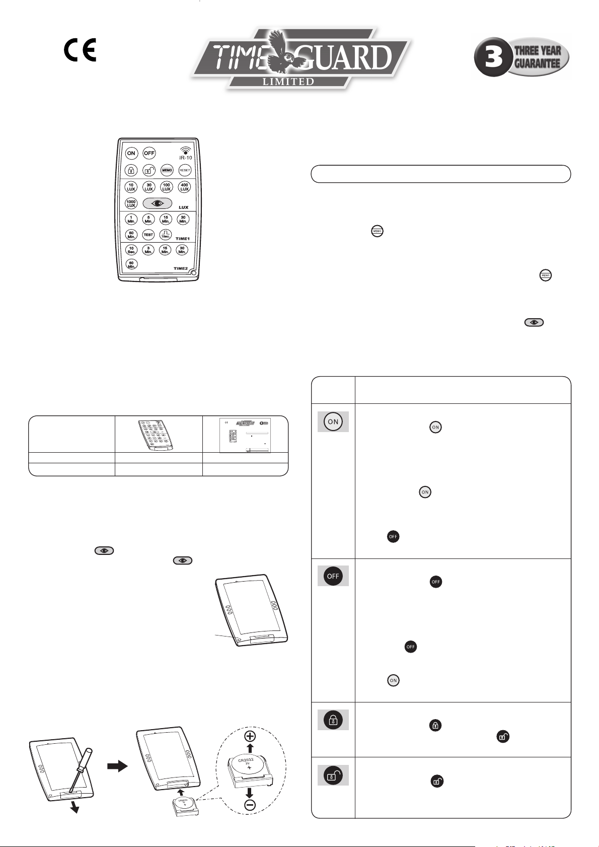
Model IR-10
• Adjustments can only be made in Unlocked Mode.
• By use of the button the operational settings mode for one unit
can be loaded into other units in the same area.
It also allows return to previous operational settings after a Reset.
• The maximum IR transmit time when a button is pressed is 1 second,
pressing a button for longer than this is not effective.
• Pressing more than one button simultaneously will result in a failed
transmission.
• Commands and operational settings are all confirmed by around
2 seconds of rapid flashing of the sensor LED except for
(see relevant section).
• Time setting for load II (HVAC) is only available with PDSM362 and
PDFM362.
Push
Button
Function
Sensor load I ON
IR Remote Control IR-10 Instructions
1
Package Contents
4 Push Button Function
Technical Specifications
Rated Voltage: 3V DC (CR2032 battery)
Transmission Range: Approx. 3M
Transmission Angle: 35º
Operating Temperature: 0ºC to +45ºC
Storage Temperature: -25ºC to +55ºC
Conforms To EC Directives
Note
Conforms To EC Directives
IR Remote Control IR-10 Instructions
Model IR-10
Technical Specifications
Rated Voltage: 3V DC (CR2032 battery)
Transmission Range: Min. 4m (IR-10 directly below detector)
Transmission Angle: 35º (above range is reduced to approx.
3m at extremes of transmission angle)
Operating Temperature: 0ºC to +45ºC
Storage Temperature: -25ºC to +55ºC
Package Contents
1
Visual I.D.
Item Remote Control Instructions
Quantity 1 1
2 Features
2.1 No need for climbing up ladders, the ceiling mounted presence
detector can be adjusted and set up easily by a user with an IR-10.
2.2 By pressing “ “ button the actual light level can be read-in to
the sensor. (Refer to function of “ “ button).
2.3 The IR-10 can be attached to a
Fig. 1
key ring chain for convenience.
(See Fig.1)
2.4 To render the IR-10 operational
remove the battery isolating
strip by pulling the exposed
tab away from the IR-10 body.
Key Chain
Hole
3 Battery Replacement
Lever out the battery holder with a screwdriver, then replace the battery
(type CR2032 3V). Please make sure the battery is the right way up,
then push the battery holder back. (See Fig.2)
4 Push Button Function
Note
• Adjustments can only be made in Unlocked Mode.
• The sensor may be set to continuously ON or OFF for 8 hours as well
as detection mode controlled by or independent of light level.
• By use of the button the operational settings made for one unit
can be loaded into other units in the same area.
It also allows return to previous operational settings after a Reset.
• The maximum IR transmit time when a button is pressed is 1 second,
pressing a button for longer than this is not effective (except ).
• Pressing more than one button simultaneously will result in a failed
transmission.
• Commands and operational settings are all confirmed by around
2 seconds of rapid flashing of the sensor LED except for
(see relevant section).
• Time setting for load II (HVAC) is only available with PDSM362 and
PDFM362.
Push
Button
(Command)
(Command)
(Command)
Sensor load I ON
• By pressing the “ “ button load I will be switched
on for 8hrs, this is confirmed by around 2sec rapid
flashing of the sensor LED. The sensor LED flashes 1sec
ON and 5sec OFF during the ON mode. No movement
can be detected by the sensor during the ON mode.
• Exit the ON mode and return to Auto mode either by
pressing the “ “ button (confirmed by around 2sec
rapid flashing of the sensor LED) or by re-supplying
power after it has been turned off for at least 10 seconds.
• Load I can be switched to the OFF mode by pressing
the “ “ button during an ON period (confirmed by
around 2sec rapid flashing of the sensor LED).
Sensor load I OFF
• By pressing the “ “ button load I will be switched
off for 8hrs, (confirmed by around 2sec rapid flashing
of the sensor LED). The sensor LED flashes 1sec ON and
5sec OFF during the OFF mode. No movement can be
detected by the sensor during the OFF mode.
• Exit the OFF mode and return to Auto mode either by
pressing “ “ or to re-supply power after it has been
turned off for at least 10sec.
• Load I can be switched to the ON mode by pressing
the “ “ button during an OFF period (confirmed by
around 2sec rapid flashing of the sensor LED).
Locking of IR-10
• By pressing the “ “ button the IR-10 can be locked
and no button will function except “ “. It is confirmed
by around 2sec rapid flashing of the sensor LED.
Function
Fig. 2
Unlocking of IR-10
• By pressing the “ “ button the IR-10 is unlocked,
(Command)
(all buttons will now function). This is confirmed by
around 2 sec rapid flashing of the sensor LED.
Page 2
Push
Button
(Operational
Setting)
(Operational
Setting)
Function
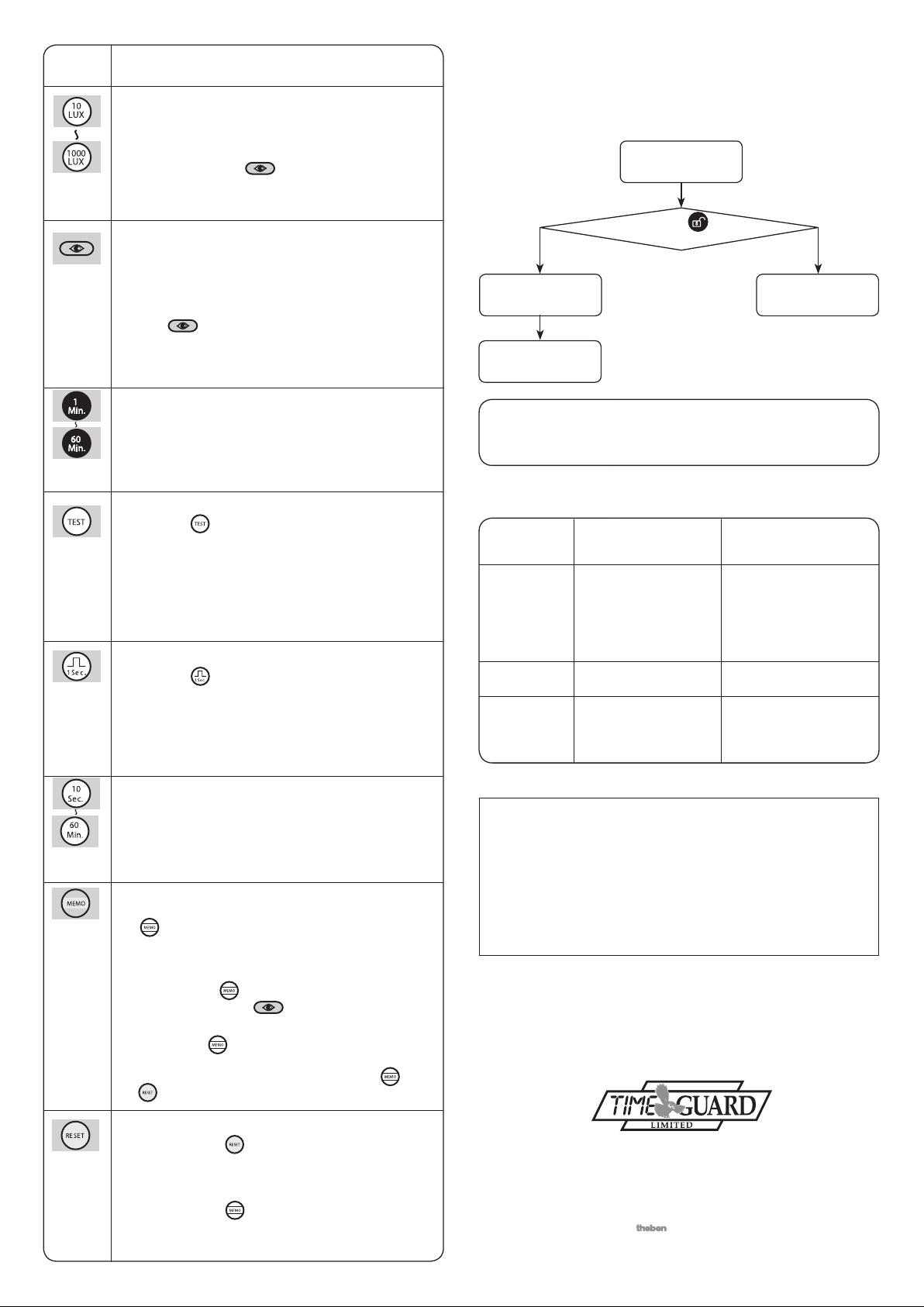
Lux value adjustment for load I
• The operating light threshold, below which the unit
will be functional in Auto mode, can be selected by
pressing one of this group of buttons (an alternative
can be chosen – see ).
• This is confirmed by around 2sec rapid flashing of the
sensor LED.
Automatic read-in of actual light level as the
threshold of switching for load I
• If the set lux values do not match the user’s required
value the actual light level can be read-in as the
threshold for switching load I. The steps are as below:
• Push “ “ button till sensor LED flashes slowly for
10sec while the unit learns the actual light level. This is
confirmed by both load and LED turning ON for 5sec.
Then the unit returns to Auto mode.
5 Trouble Shooting
If the IR-10 remote control does not work follow the flow chart in 5.1.
5.1 Trouble shooting for IR-10 only
Adjustments do
not work.
Press “ “
button.
Adjustments do
not work.
Replace battery.
Adjustments work
successfully.
(Operational
Setting)
(Operational
Setting)
(Operational
Setting)
(Operational
Setting)
(Operational
Setting)
Time setting for load I - lighting (Time I)
• By pressing the corresponding button, the required
delay time for load I can be set, it is confirmed by 2sec
rapid flashing of the sensor LED.
Test mode
• Press the “ “ button to enter Test mode, it is
confirmed by 2sec rapid flashing of the sensor LED.
Walking through the detection coverage, both load I
and the sensor LED turn ON for 2sec then OFF for at
least 2sec once sensor is triggered. The unit works at
all lux values.
• Load II does not operate in Test mode.
Short impulse mode
• Press the “ “ button to enter Short impulse mode, it
is confirmed by 2sec rapid flashing of the sensor LED.
When the light level is below the selected
threshold and the sensor is triggered, load I will turn
ON for 1sec then OFF for at least 9sec.
• Load II does not operate in Short impulse mode.
Time setting for load II - HVAC (Time 2)
• By pressing the corresponding button, the required
delay time for load II (HVAC) can be set, it is confirmed
by 2sec rapid flashing of the sensor LED.
Store and duplicate of the values set by IR-10
• When Time or Lux has been set by the IR-10 press the
“ “ button for more than 3sec, and the sensor LED
flashes for 2sec rapidly to confirm settings have been
stored. If no settings for Lux or Time have been made
the sensor LED does not flash in response to the 3sec
pressing of the “ “ button and no settings are stored.
(Light level set by the “ “ button can not be stored).
• The IR-10 may now be taken to another sensor and by
pressing the “ “ button for around 1sec the stored
settings will be duplicated in the second sensor.
Note: Please read Reset (below) to see how “ “ and
“ “ work together.
Note
All the adjustments set by IR-10 will be erased after battery
replacement, please set values again.
5.2 Trouble shooting for IR-10 combined with sensor
Problem Possible Suggested
Cause Solution
Failure to
receive
signal.
No signal.
Fail to
transmit
signal.
Transmission range
exceeded.
IR-10 battery is low.
IR-10 is in locked
mode.
Operate within specified
transmission range, and
ensure IR-10 is aimed
within the 35º reception
angle of the detector.
Replace battery.
Unlock IR-10.
3 Year Guarantee
In the unlikely event of this product becoming faulty due
to defective material or manufacture within 3 years of the
date of purchase, please return it to your supplier in the
first year with proof of purchase and it will be replaced
free of charge. For years 2 and 3 or any difficulty in the
first year telephone the helpline on
For assistance with the product please contact:-
HELPLINE
020-8450-0515
or email helpline@timeguard.com
020 8450 0515.
(Command)
Reset
• By pressing the “ “ button the sensor is returned to
operation controlled by the dial settings on the side of
the sensor. It is confirmed by 2sec rapid flashing of the
sensor LED.
• By pressing the “ “ button again for around 1sec
the sensor returns to be controlled by the last settings
previously set by the IR-10.
For a product brochure please contact:
Timeguard Ltd.
020-8452-1112
or email csc@timeguard.com
A Group company
67-058-278 (Iss. 2)
 Loading...