

Page 1
High Frequency
Sensor
Model: HF1
Installation & Operating Instructions
Page 2

1. Specifications:
1. Power: AC 220 ~ 240V 50MHz.
2. Sensor Technology: 5.8GHz High Frequency.
3. Switching capacity: 1000W Incandescent or Halogen / 500VA
Fluorescent or Low Energy.
4. Angle of coverage: 360° with 160° angle of aperture.
5. Lux setting: 1 ~ 2000 Lux.
6. Time setting: 3 sec to 30 min.
7. Manual override: Switchable (4 Hours).
8. Warm up: 60 sec.
9. Indoor use only.
2. Adjustments:
1. TIME: The detector has an adjustable TIME ON control from 3 sec.
to 30 min. Move the time indicator fully anti-clockwise for the shortest
time (approx 3 sec). Move the time indicator fully clockwise for the
1
longest time (approx 30 min). The timer starts working after the last
detected movement. See Fig. A.
2. RANGE: The sensor has a detection range which is adjustable
from 0.5m to 6m. Move the range indicator fully anti-clockwise for the
minimum setting (0.5m). Move the range indicator fully clockwise for
the maximum setting (6m). See Fig. B.
3. LUX (light level): It can be set to any level between 1 – 2000 Lux.
Move the lux indicator fully anti-clockwise for night time operation
(approx 1-8 Lux). Move the lux indicator fully clockwise for daylight
operation (approx 2000 Lux). See Fig. C.
Fig. A Fig. B Fig. C
®
Page 3
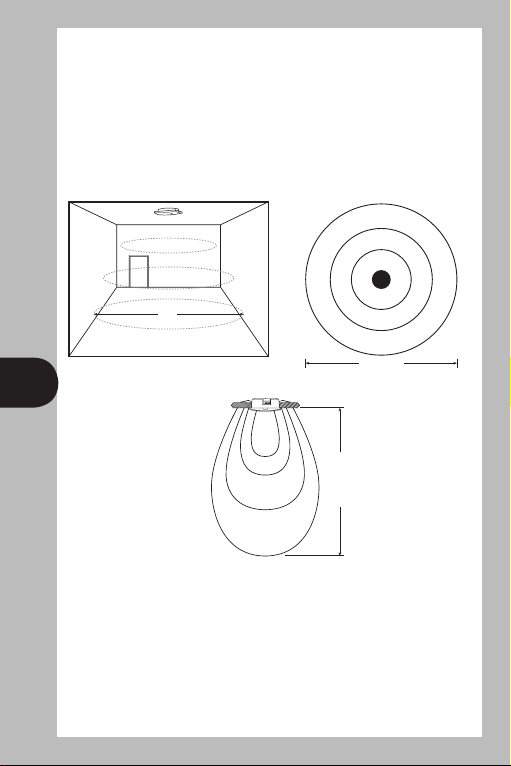
3. Detection Range:
L’ N L N
The integrated HF sensor emits high-frequency electromagnetic waves
(5.8GHz) and receives their echo, any change in echo is perceived by
the sensor and will indicate the presence of a person(s) or animal(s).
A microprocessor triggers almost without any delay and will activate the
connected lights or applications. Detection is able to pass through glass,
doors and around partitions with 360 degree coverage. See Fig. D, E.
6m
2
Fig. D
L’ N L N
Max. 3.6m
4. Safety Instructions:
1) Disconnect the power supply before any installation.
2) During the installation, the power cable must be voltage-free when
connected. Therefore we recommend you switch off the power and
check there is no voltage with a voltage tester – before you start.
3) Please note that the sensor must be protected by a 5A circuit breaker.
4) The mains cable needs to be 0.5~1.5mm².
Min. 6m
h=2.4~3m
Fig. E
Page 4

Min. 6m
h=2.4~3m
Max. 3.6m
L’ N L N
Min. 6m
h=2.4~3m
Max. 3.6m
L’ N L N
6m
Min. 6m
h=2.4~3m
L’ N L N
3
4. Ceiling Flush-Mount Installation:
Warning: If you have any doubts about the installation, please ask a
qualified electrician to install it and ensure that the sensor is screwed
securely to the ceiling without any movement.
Ø112mm
1. Determine the best location for the sensor.
2. Drill a hole of 112mm in diameter in the ceiling. The thickness of the
ceiling must be between 5 and 25mm. See Fig. F.
3. Connecting the power supply. Please refer to the subject of
“Connection to the power supply” in page 5 and the wiring diagram.
See Fig. J.
4. Please remove the metal mounting feet from the accessory pack and
clip on the HF1. Make sure the mounting feet is clipped to the correct
position. See Fig. G.
5. Adjust the metal mounting feet vertically first (Fig. H) and then push
the HF1 upward into the hole until the mounting feet holds the ceiling
and the unit in place. See Fig. I.
6. Adjust TIME, LUX and RANGE controls. Please refer to the subject of
“Initial set up and operation” in page 5.
Fig. GFig. F
Page 5

L’ N L N
L’ N L N
Fig. H
L’ N L N
L’ N L N
4
Fig. I
Note:
1. The ideal height for sensor is between 2.4m to 3.0m.
2. Please do not install in a location, which is subject to water spray,
rain or wet conditions.
3. Please do not install in a place where the sensor’s performance will
be masked by metal objects in front of the sensor. It might affect the
total detection distance.
Page 6

5. Connection to the Power Supply:
L’ N L N
Important:
1) Note: This sensor must be installed according to local Wiring
Regulations and Code of Practice.
2) Ensure the supply is disconnected at the distribution board before
beginning with the electrical wiring. If in doubt, the cables must be
checked with a voltage tester.
3) Study the wiring diagram below before making any electrical
connections. Incorrect wiring of the unit could destroy the sensor.
Connection:
1) The mains supply is connected to the AC IN terminals marked L (Live)
and N (Neutral). See Fig. J.
2) The output (or Load) is connected to the LOAD terminals marked
L’ (Switch Live) and N (Neutral). See Fig. J.
5
L’ N L N
L’ N L N
Load
Initial set up and operation:
AC IN
220V ~ 240V
Fig. J
After 4 Hours or switch
Off 2 Sec. and ON
Switch
Power On Auto Switch 2 x Permanent
Off Mode Off and On On
Page 7

1) When powered on (after the 60 seconds warm up) the sensor
goes into the auto mode. Please open the front cover and turn the
TIME setting to its minimum and the LUX setting to its maximum
in order to test.
2) Walk in front of detector until light comes on. This checks the
operation of the detector and the field of view.
3) Turn the TIME and LUX to the desired positions.
4) To switch the light permanently ON (4 hours max), switch OFF
and ON twice in rapid succession within in the range of 0.5 sec
to 2 sec. This will change the HF1 from auto mode to manual
override mode.
5) The sensor will automatically turn off after 4 hours or by switching
power switch OFF for 2 sec and ON again.
6) The LED will flash 3 times when sensor goes into auto mode.
Note: If LED is still on, it means it is in override mode;
make sure to switch off power for more than 2 sec.
When in override mode, the LED will be on permanently.
6
6. Trouble Shooting:
Malfunction Cause Solution
Sensor without power Fuse blown, Replace fuse and switch ON
not switched ON mains switch. Check supply
with voltage tester
Short circuit Check connection
Sensor does not Fuse blown Replace fuse and check
switch ON connection if necessary
Bulb blown Replace bulb
Lux setting in night time Readjust Lux setting
mode during daytime
operation
Sensor does not Detect continued Check detection area
switch OFF movement in detection range
Permanent light ON Switch off permanent light
Sensor switch keeps Curtains, pets, etc… Check detection area
switching ON and OFF
Page 8

3 Year Guarantee
In the unlikely event of this product becoming faulty due
to defective material or manufacture within 3 years of the
date of purchase, please return it to your supplier in the
first year with proof of purchase and it will be replaced free of charge.
For years 2 and 3 or any difficulty in the first year telephone the
helpline on 020 8450 0515.
For assistance with the product please contact:
HELPLINE
020 8450 0515
or email helpline@timeguard.com
For a product brochure please contact:
Timeguard Limited.
Victory Park, 400 Edgware Road,
London NW2 6ND
Sales Offi ce: 020 8452 1112
or email csc@timeguard.com
Zerofour – February 2012
Designed in the U.K. 67-058-474
 Loading...