

Page 1
Installation & Operating Instructions
WiFi Controlled Fused
Spur Time Switch
Model: FSTWiFi –
WiFi Controlled Fused Spur
M
odel: FSTWiFiTGV –
WiFi Controlled IP66 Fused Spur
Page 2

1
1. General Information
These instructions should be read carefully and retained for further
reference and maintenance.
Note: Timeguard reserve the right to alter these instructions, and the
SupplyMaster app, at any time. Up to date instructions will always be
available for download at www.timeguard.com.
2. Safety
• Before installation or maintenance, ensure the mains supply to the
time switch is switched off and the circuit supply fuses are removed
or the circuit breaker turned off.
• It is recommended that a qualified electrician is consulted or used
for the installation of this thermostat and install in accordance with
the current IEE wiring and Building Regulations.
• Check that the total load on the circuit including when this
thermostat is fitted does not exceed the rating of the circuit cable,
fuse or circuit breaker.
• To clean use a clean dry cloth only. Do not use liquid cleaners.
3. Technical Specifications
• Mains Supply: 220-240V AC 50Hz
• Fused: Supplied with BS1362 13A Fuse
• Rocker Switch: 2 Pole, providing isolation
• Switch Rating: 13A Resistive (3kW)
1000W Incandescent, Halogen lighting
500W Fluorescent, LED lighting
100W Compact Fluorescent lighting
• Contact Type: Normally Open, micro disconnection
Page 3
2
• Wi-Fi Specification: 2.4 GHz b/g/n
• Frequency Range: 2.412 – 2.484 GHz
• Operating Modes: Permanent ON or OFF, Auto timed, Holiday
• Boost Times: 1 or 2 hour
• Output Light: Yes
• Operating Temperature: 0°C to +40°C
• IP Rating: FSTWiFi – Intended for indoor use only
FSTWiFiTGV – IP66 rated suitable
for restricted external applications
• Minimum Depth of Wall Box: 25mm
• Multiple Device Support: Yes
• CE Compliant
• Dimensions: H = 85mm, W = 85mm, D = 44mm
Note: Not suitable for use with Discharge Lighting.
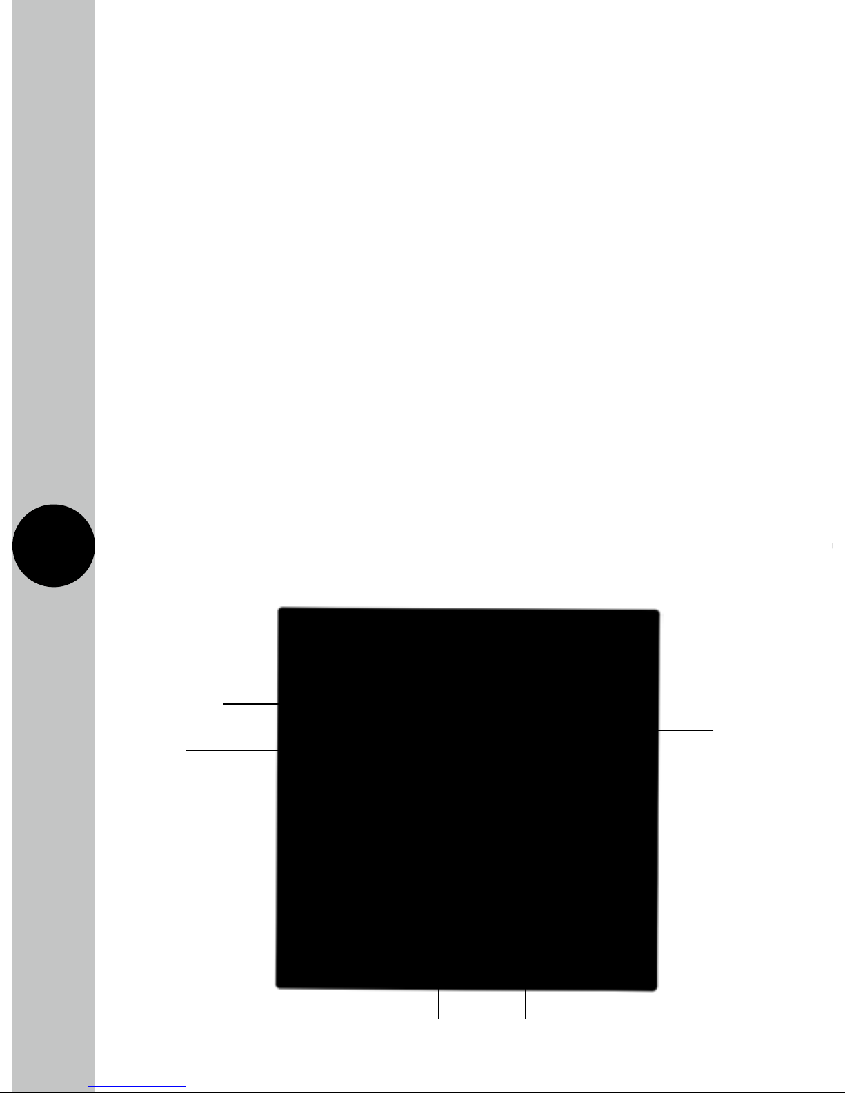
ON/OFF
indicator
Override
button
and Wi-Fi
connect
Wi-Fi
connection
indicator
Double pole switch BS1362 (1" x 1/4") fuse
Page 4

3
FSTWIFI MAC address and ID Wi-Fi number label
Important: Do not remove this label from the side of the product.
4. Contents
FSTWIFI
• 1x FSTWIFI time switch
• 2x Mounting screws
• 1x Cable clamp
• 1x Cable blank
• 1x Instruction manual
Note: all instructions are to be left with the customer after installation.
5. Installation
FSTWiFi – Wi-Fi Controlled Fused Spur
Note: The unit is designed to replace an existing single gang connection unit
or fixed appliance outlet giving timed mains output, protected by a BS1362
fuse. The unit is capable of forming part of a ring main (the terminals can
accept 2x 2.5mm sq. cables), or terminating a spur off the ring main.
The unit requires a minimum depth of 25mm within the box.
5.1 Ensure the mains supply is switched off and the circuit supply
fuses are removed or the circuit breaker is turned off.
FSTWIFITGV
• 1x FSTWIFITGV time switch
• 2x 20mm cable glands
• 1x Instruction manual
Page 5
4
5.2 Connect the incoming 230V 50Hz mains supply and outgoing
load cables to the relevant terminals ensuring correct polarity
is observed and that all bare conductors are sleeved
(see section 6. Connection Diagram).
5.3 There is a removable cable blank to cover the front cable exit
if this feature is not required.
5.4 If the front cable exit is required, for instance to connect to
a washing machine, use one of the cable clamps provided
to secure the outgoing cable.
5.5 Secure the unit to the back box with the M3.5mm screws provided,
forming cables during installation to avoid entrapment, and
cable damage.
FSTWiFiTGV – Wi-Fi Controlled IP66 Fused Spur
5.6 IMPORTANT Switch off the electricity at the fuse box by removing
the relevant fuse or switching off the circuit breaker before
proceeding with the installation.
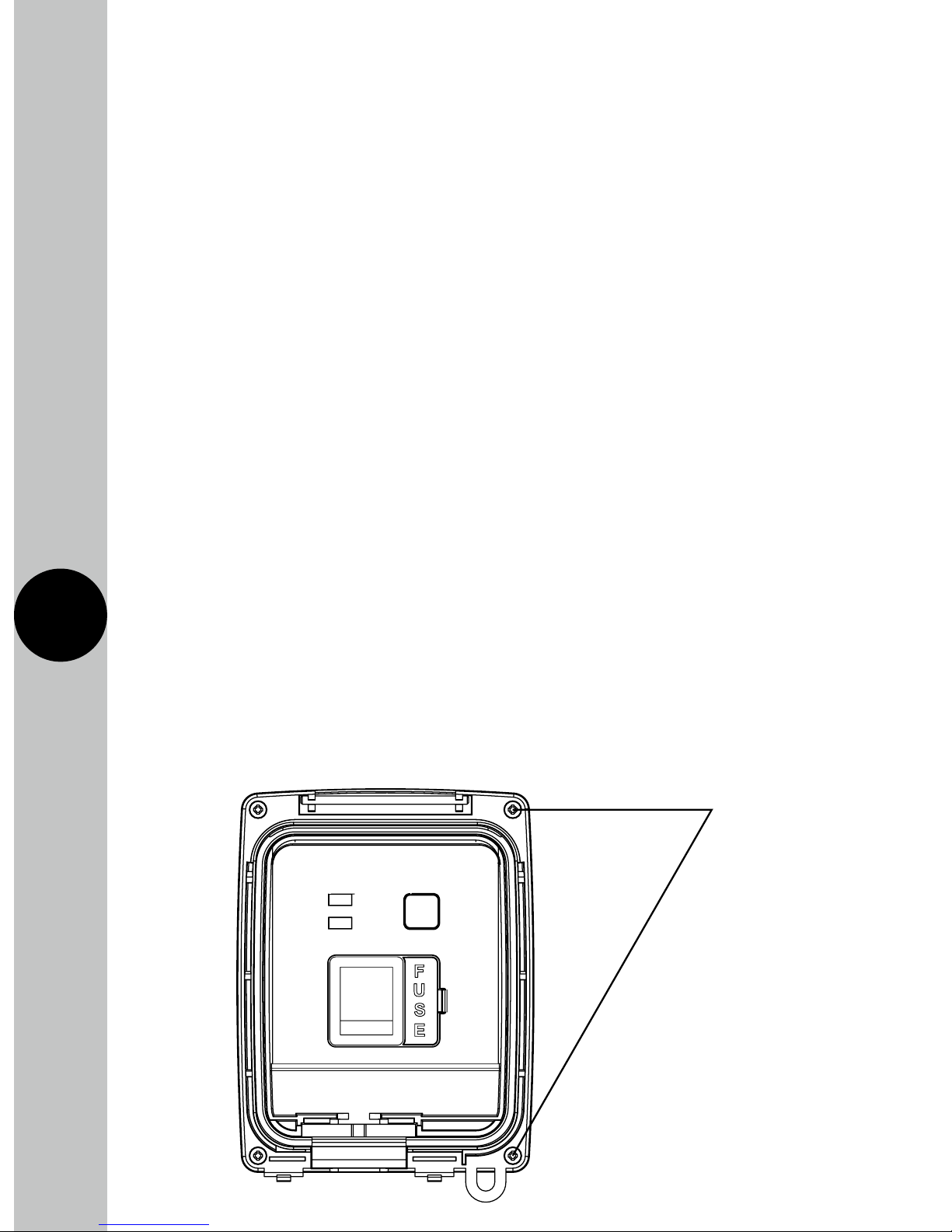
5.7 Using a Phillips screwdriver, separate the faceplate from the back
box by removing the four tapped screws located in each corner.
Tapped
screws
Page 6

5
5.8 Using the back box as a template mark the position for the holes.
Note the back box must be mounted in the correct orientation,
following the ‘TOP’ marking inside the back box. If the mounting
position desired is uneven use a sheet of marine ply as a base plate
and fit the back box.
5.9 Drill the wall using a 4mm Ø drill bit making sure not to infringe
or compromise any gas, water pipes or cables. Insert the rawl
plugs into the holes.
5.10 The drain feature must be drilled out using a 5mm drill bit if the top
or side entry conduit is used. Opening this drain hole will reduce
the IP rating of the product. Only the lower drain feature on the
back box must be opened.
5.11 Select the required entry point by unscrewing the appropriate
seal located on all four sides of the back box. If conduit is not
going to be used, a waterproof cable with suitable rated 20mm
glands will be required to maintain the overall IP rating. If the
bottom entry conduit is used, there must be adequate drainage
from the lowest point of the conduit.
5.12 Secure the back box to the wall using suitable screws for the rawl
plugs installed. Ensure that the back box is correctly orientated
following the ‘TOP’ marking which is labelled inside.
5.13 Pass through the 230V AC 50Hz mains supply cable and secure
the cables tightly to their respective terminals, ensuring that all
bare conductors are sleeved and that correct polarity is observed.
Note that if metal conduit is used the earth continuity between
the conduits must be maintained.
5.14 Once the mains supply is connected to the correct terminals,
mount the face plate to the four mounting holes on the back box.
Tighten until secured.
Page 7
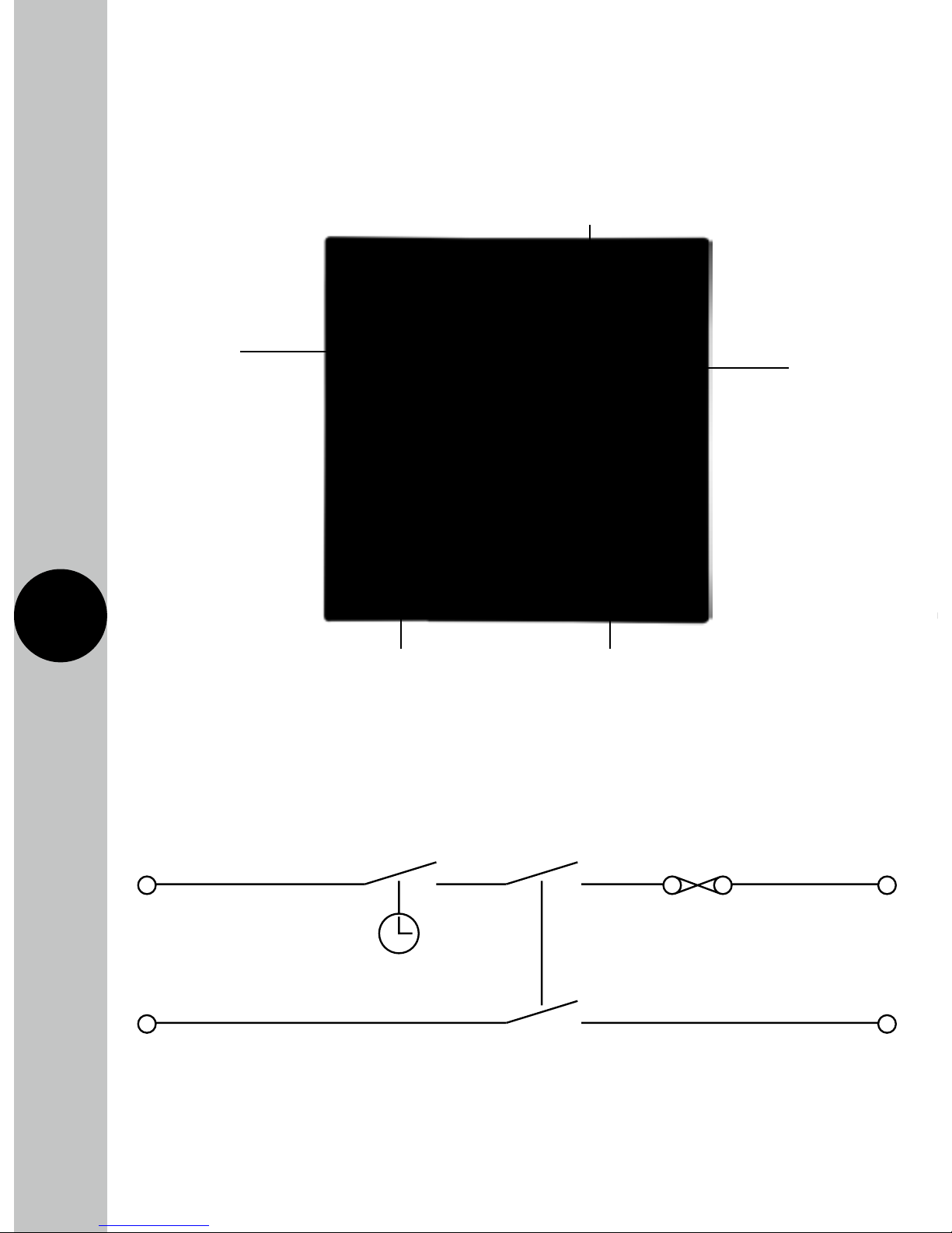
230V AC 50Hz
MAINS SUPPL
Y
BROWN
L OUT
BROWN
L IN
BLUE
N OUT
BLUE
N IN
BS1362 Fuse
Timeswitch
Double Pole Switch
APPLIANCE
6
Switched Live Terminal Load
live connection – Brown
Mains Supply
Terminal
Live – Brown
230V 50Hz
Switched Neutral Terminal Load
Neutral connection – Blue
Loop terminal for earth
continuity Green/Yellow
Mains Supply
Terminal
Neutral –Blue
Internal Schematic
6. Connection Diagram
• The terminals are marked as follows on the rear of the time switch;
Page 8

7
7. Setup
Note: the mobile or tablet device must be connected to a 2.4GHz band
on the router. Pairing on the 5GHz band will result in paring either timing
out or being unsuccessful. Refer to your ISP (Internet Service Provider)
on separating the bands if required.
7.1 Ensure your phone or tablet is connected to your
local Wi-Fi network.
7.2 Download the Timeguard Supplymaster App onto your phone
or tablet by searching for Timeguard on Google Play or the
App Store. You can also scan the QR code below applicable
to your device.
Page 9

8
7.3 Install the App, and open it to the registration page.
7.4 Users must first register, and then log in to use the app.
First time users must use the main account log in.
Note: Usernames and passwords cannot contain any
spaces or special characters, and must use letters
and numbers only.
7.5 Then, press the + button (bottom right on the phone’s screen
to open the add devices menu).
7.6 The network the mobile or tablet is connected to will be shown
on the App, enter the password for the network SSID.
Important – DO NOT PRESS START AS OF YET.
7.7 After entering the password for your Wi-Fi network, name
the device you want to add to your account.
Note: Device names cannot contain any spaces
or special characters
7.8 On the FSTWiFi/FSTWiFiTGV, hold down the override button,
until the blue LED light starts to flash.
7.9 Once the blue LED is flashing press start in the App.
The App will search for an available device.
7.10 Once the App has found and configured the FSTWiFi/FSTWiFiTGV
to the network and your account your device will show up in the
devices menu. The blue LED will become solid when there has
been a successful connection to your Wi-Fi network.
Note: If the device is to be sold, it must be deleted
from the App by the main account holder. The device
can only be registered to one account at a time.
Page 10

9
10
8. Features of the FSTWiFi/
FSTWiFiTGV Device
Micro Disconnection
• The unit offers micro disconnection of the load using the programmed
times, or full isolation using the double pole rocker switch on the front
of the unit.
• Micro disconnection can also be applied using the override switch
on the front of the unit. Fused protection is also provided.
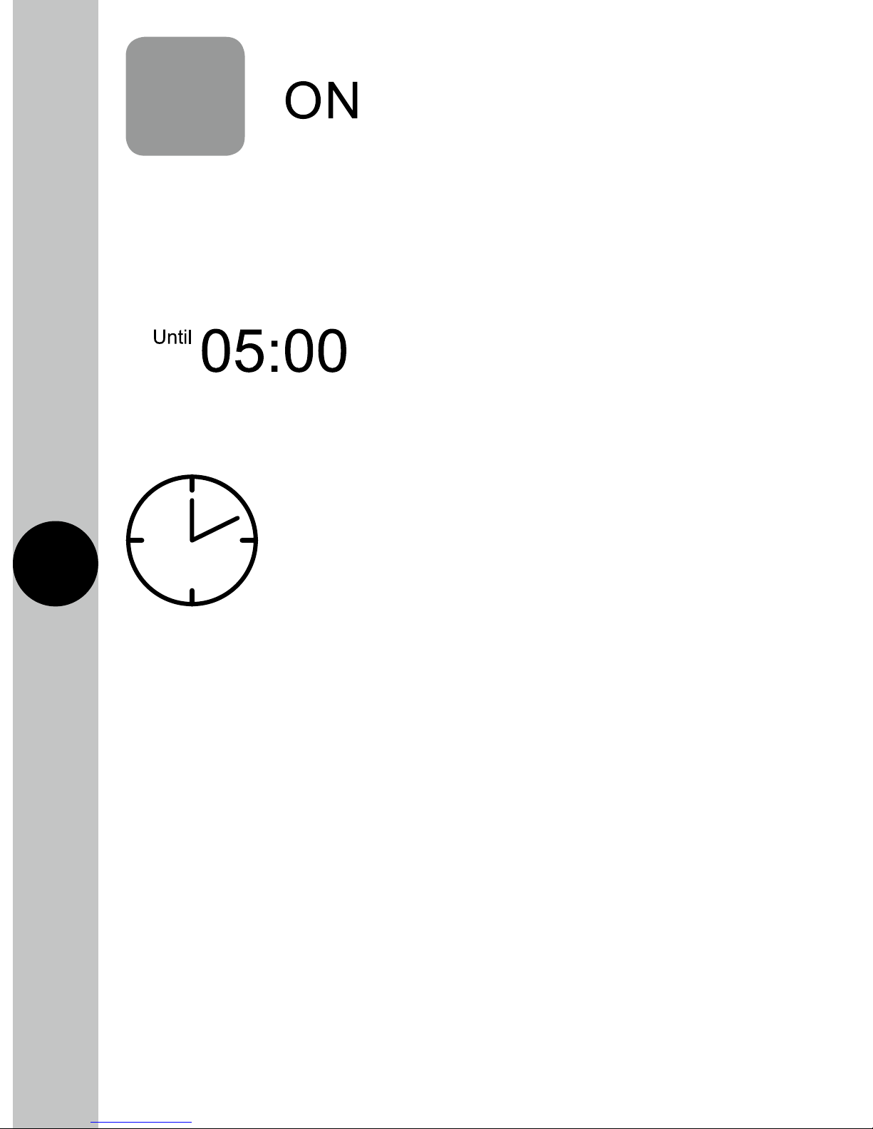
Manual Override
• The override button on the front of the unit provides a permanent
OFF, or ON, until the button is pressed again. It is not overridden
by the next program from the App.
• During the overridden period, the App will show permanent ON,
or permanent OFF. The override can be cancelled in the App by
putting the mode back to Auto Timed.
Light Indicators
• Red ON/OFF indicator. The red light will turn ON when there is
output, and will turn OFF when there is no output. The red light
will flash if there is output, but there is no output load detected.
• Blue Wi-Fi connection indicator. This will illuminate when the device
is connected to Wi-Fi, as detailed in section 7. Setup. This indicator
will flash only when attempting to connect to the server.
Page 11

10
9. Features of the Android
and iOS App
General
• The app can be accessed, and the device controlled from any
accessible Wi-Fi zone. Once Wi-Fi is set up on the device, the App
can also control the FSTWiFi/FSTWiFiTGV through 4G. The device
must be connected to a Wi-Fi network.
• There are useful programming tips and help available on the
Timeguard YouTube channel. You can access the link directly from
our website www.timeguard.com or go to the YouTube home page
and search ‘Timeguard’.
Page 12

11
12
Back
button
Settings
Mode
indicator
Output
indicator
Boost
Button
Device name
Time of next
program
change
Advance
button
Program
entry
Device Home Screen
• From log in, the user is presented with a list of devices.
Each of these has a device home screen.
When a device is selected, the home screen is then shown.
Page 13

12
13
Operating Modes
• The following options are available in mode settings through
the device home screen
:
Auto: Output is controlled by the timer programme, and can
be temporarily overridden by boost or advance.
Permanent OFF: Output will remain off until auto is re-enabled
by the user. In this mode, boost and advance are disabled.
Permanent ON: Output will remain on until auto is re-enabled
by the user. In this mode, boost and advance are disabled.
Holiday: Output is off until the date entered by the user, at which
time the program schedule will default back to running as normal.
• Only one mode can be selected at any time. Permanent OFF, ON,
and holiday can be cancelled by returning the App to Auto mode.
Boost
• From OFF, a one or two hour boost can be set using
the boost button. A third press of boost will cancel.
• The duration of the boost is shown on the device home screen,
and this will count down the time to the end of the boost period.
• From ON, a one or two hour boost can be added to the programmed
end time. This is shown on the device home screen.
Note: Boost will not cross midnight.
Page 14
13
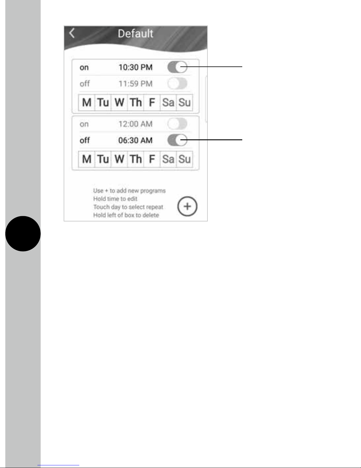
Program Entry
• The App supports multiple programmed times, with an easy repeat
function for different days. Up to 6 times can be added to a program
set if required (using the plus key).
• Time entry is programmed via the program key on the device
home page. Hold the chosen time down to edit the times, hold
the day MTWTFSaSu to change repeats, or hold the left side of
the time box to delete the entire program set via the confirm button.
• The default times are 06:00 to 08:00, and 18:00 to 20:00 every day.
• Times can be programmed across midnight. Enter a start and end time
before midnight. Enter a second set of times after midnight. Turn off
the first end time and second start time using the green sliders.
Set the repeats.
Advance
• Advance changes the output state until the next
programmed change.
Note: The display will show the next program change:
• The time of the next programmed change is shown on the device
home screen. It also shows the boost time in boost mode (see above).
Page 15
14
Quick Programming Tips
• Up to 6 ON/OFF periods are allowed per program set with
weekly repeats.
• Days can be selected and deselected by touching the day required.
• If a day is deselected, it shows grey; this would mean that after the
last program off time for the selected day ends, no programs will
be active until the next selected day within the alternative program set.
Alternative Program Periods
• The App supports multiple alternative programs. This is useful
for keeping separate sets of programs, for use in school holidays,
periods of non-residency, pre and post summer time, seasonal
programs, and periods of unexpected residency such as illness.
This means that the original time programs can be saved, and
reverted back to when needed, without the need for reprogramming.
Start Time 10:30PM
Repeats (MTWTF)
End Time 06:30AM
Repeats (MTWTF)
Page 16

15
16
• Hold the program name to edit or delete, and use the plus key
to add new programs.
12/24 Hour Clock
• Times can be shown in either 12 or 24 hour format, in Advanced Settings.
Clear ON/OFF Status
• The device home screen clearly shows output status through
both text (ON/OFF), and colour change of advance button
(Red OFF, Green ON).
Supports Multiple Users
• Additional users can be added by the Main Account holder,
in Advanced Settings, to allow sub account users to control
the device.
• Users can be both added and deleted by the Main Account holder
only. All other features of the App are the same. Users are deleted
by swiping their name to the left, in the remove users menu which
is an option in Advance Settings.
• Only one Main Account can be registered per device. Sub Account
users would use the sub account login option on the login page
of the App.
Positive Affirmation of ON/OFF Status
• With output status not enabled (default), the advance button shows
red OFF, green ON.
• Output status will not work unless there is more than 10W, the
advance button will remain red, but show the word ON to show that
it is programmed ON period, but the device cannot detect the load.
• Output status shows that the device is working, and will only show
a change of state if there has definitely been a change of output
state (above 10W).
Page 17

16
17
• With output status enabled, the advance button will show what
is happening with the output. There is an icon on the home screen
which shows that this feature has been enabled.
• If there is no load detected during an on period, the advance
button will show red, ON. This is a fault condition as the output
is not detected.
• Once the output has been detected, the advance button shows
green, ON.
• If there has been a load measured at some point in the ON period,
but the output can no longer be detected, the indicator will show
orange (standby), until the load is detected again, when it will show
green. This is common when the output has a secondary control
option, such as a thermostat or isolation point between the FSTWiFi/
FSTWiFiTGV and the appliance. Refer to the no load indicator guide
video on our YouTube channel for more information on this.
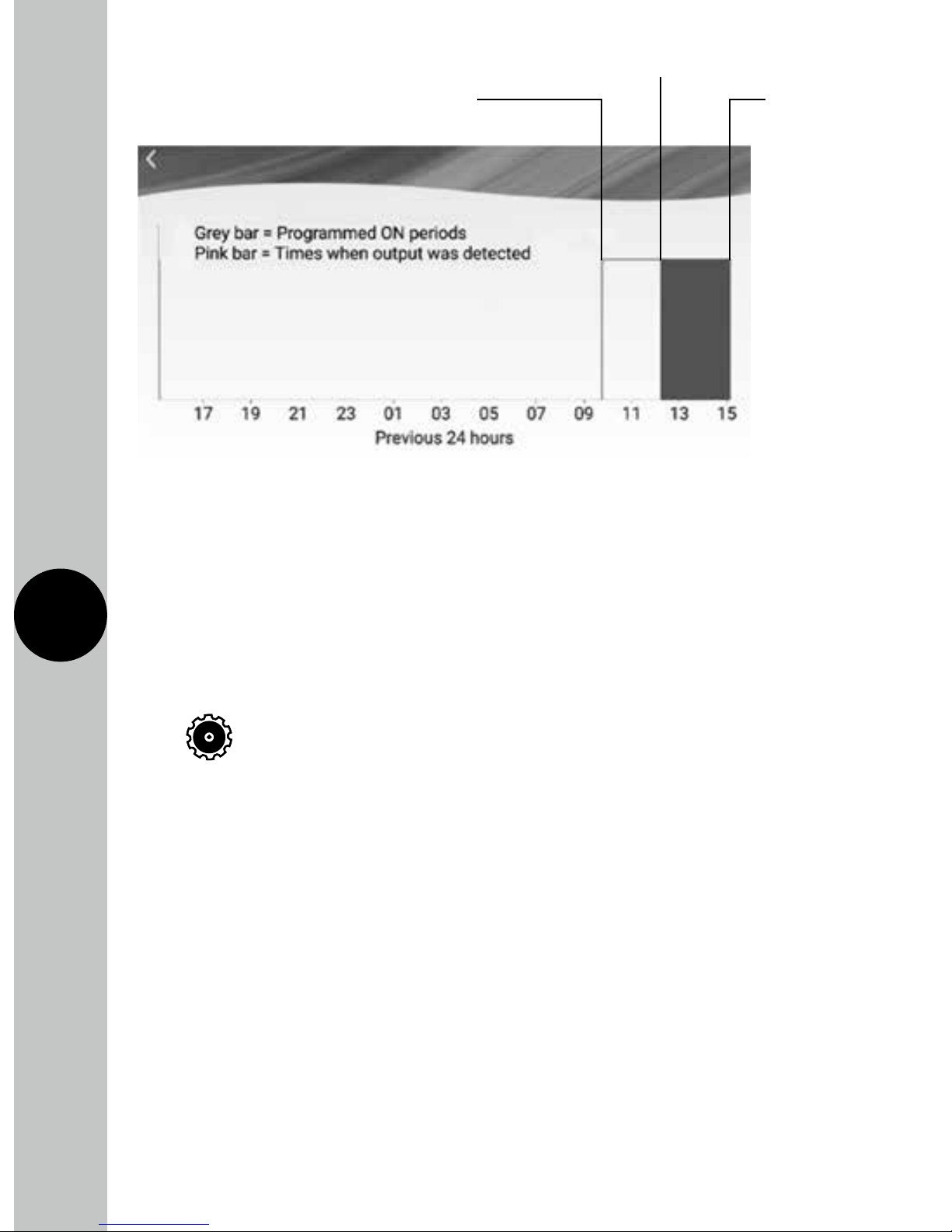
Graphical Representation of the Last 24 Hours
• With output status enabled, there is a graphical representation that
compares programmed on times with actual output. This can be used
to check the FSTWiFi/FSTWiFiTGV (and the connected appliance)
have been working correctly.
• For appliances with additional controls (for instance thermostats),
the output load is not consistently on during the programmed
on period. The graphical representation will show this difference.
Pink bars represent when there was an output, grey represents
the programmed times.
Historical Summary
• There is a brief summary of the last ON period, showing the duration
of the period, and the length of time there was an output.
Page 18
17
18
Advanced Settings
The advanced settings menu can be found on the devices page via the
icon
and can do the following:
• Add User: Allows the main account holder to add additional users
known as sub account users. Subaccount users can manipulate the
control aspects of the FSTWiFi/FSTWiFiTGV but will not be able to
delete the device from the main holder’s account. Subaccount users
must register via the users’ option in the advanced settings menu
while the main account holder is logged in, this way the App will
register any subaccount user to the main account holder’s device.
IMPORTANT Subaccount users must not register via the
registration screen when they download the App, this will
result in creating a main account.
Time Zones
• This unit is designed to be used in the UK so will come pre-set
to UK time. This cannot be altered.
Program
Start Time
Load Detected
Program
End Time
Page 19

18
3 Year Guarantee
In the unlikely event of this product becoming faulty due to defective
material or manufacture, within 3 years of the date of purchase, please
return it to your supplier in the first year with proof of purchase and
it will be replaced free of charge. For years 2 to 3 or with any difficulty
in the first year, telephone our helpline.
Note: a proof of purchase is required in all cases. For all eligible
replacements (where agreed by Timeguard) the customer is responsible
for all shipping/postage charges outside of the UK. All shipping costs
are to be paid in advance before a replacement is sent.
• Remove Users: Allows for the main account holder to remove users
from their account.
• App download: Allows the user to check which version of the App
they are using to check for updates. This feature is only available on
the Android version of the App. iOS users must update the App via
the App Store.
• User manual and FAQ: Provides links to our website, the relevant
instructions and to our YouTube channel.
• About: Provides the company address and contact details for any
problems with the unit.
• Wi-Fi Settings: Allows the user to change the router or extension
the device is connected to.
• Time format: Allows the user to change the time format between
a 12/24 hour clock.
• Privacy policy: Directs the user to the Timeguard privacy policy
page on our website.
Page 20

11
Zerofour – May 2018
67.058.560 (Issue 2)
Timeguard Limited.
Victory Park, 400 Edgware Road,
London NW2 6ND
Sales Office: 020 8452 1112
or email csc@timeguar
d.com
For a product brochure please contact:
Qualified Customer Support Co-ordinators
will be online to assist in resolving
your query.
If
you experience problems, do not
immediately return the unit to the store.
Telephone the Timeguard Customer Helpline:
HELPLINE
020 8450 0515
or email
helpline
@
timeguar
d.com
www.timeguard.com
 Loading...