

Page 1

Underfloor Heating
Systems
Installation & Operating Instructions
A choice of three underfl oor heating systems are available
in the range, each offering a variety of kit sizes, designed
for varying room and fl oor installations, enabling underfl oor
heating to be laid simply and effi ciently.
www.thermolay.co.uk
Page 2

Underfloor Heating Systems
1. Introduction
Thermolay is an underfloor electric heating system which is installed immediately under the finished
surface of tiles or stone slabs. It renders the floor surface warm to the touch and supplements other
heating in the same room.
Thermolay Comes In Three Forms:
Cable Gives the best flexibility of layout and W/m2 (heating power per unit area), but requires additional work
when laying. Three kit sizes cover areas from 1.2m
Mat Requires less work when laying than cable, but gives a fixed W/m
2
1.0m
to 5.0m2. Comes with self adhesive tape runs pre-attached for initially fixing mat to floor.
Flexi-Fast Mat This can be stretched lengthwise by 50% giving 133 to 200 W/m
with the same flexibility of layout as the Mat. Six kit sizes cover areas from 1.6m
At heat value of 200W/m2 (Flexi-Fast unstretched) can be useful in getting the best level of underfloor heating in a conservatory but
it is not possible to rely on underfloor heating alone to heat a conservatory because of the large area of glazing, particularly the roof.
In other rooms (if the building meets the latest Building regulations) it is possible to heat the room with underfloor heating alone
if 200W/m2 (Flexi-Fast unstretched) is used.
It is important that the correct size of mat/cable is used since the heating cable must not be cut. You will need to plan the layout carefully
(see section 4) prior to purchase and get the right size mat/cable for the installation. It is possible to use more than one mat/cable for an
installation by parallel connection but no cable in the system is allowed to cross over or under any other.
2
to 6.4m2.
2
of 160. Six kit sizes cover sizes from
2
. It requires the least work when laying
2
to 15.0m2.
2. What You Will Need
a. Electric Cable/Mat (one or more as required):
Cable Kits – 100 to 200 W/m
Part No Length Coverage W Ω
UFHC24 24m 1.2 to 2.4m
UFHC32 32m 1.6 to 3.2m
UFHC64 64m 3.2 to 6.4m
Supplied with a reel of securing tape.
Mat Kits (Width 0.5m) – 160W/m
Part No Length Coverage W Ω
UFHM2 2m 1.0m
UFHM3 3m 1.5m
UFHM4 4m 2.0m
UFHM6 6m 3.0m
UFHM8 8m 4.0m
UFHM10 10m 5.0m
Securing tape built into webbing.
Flexi-Fast Mat Kits (Width 0.4m) – 133 to 200W/m
(Mat Width 0.4m, length can be stretched to 150% of figures
quoted) – 133 to 200W/m
Part No Length Coverage W Ω
FFM25 2.5m 1.0 to 1.5m
FFM40 4.0m 1.6 to 2.0m
FFM60 6.0m 2.5 to 3.7m
FFM100 10.0m 4.0 to 5.0m
FFM150 15.0m 6.0 to 9.0m
FFM250 25.0m 10.0 to 15.0m
Supplied with fixing pegs.
2
b. Controller
Installations without temperature control could give a floor
temperature of around 55°C which is not dangerously hot but is
wasteful of energy.
There are three controllers (temperature probe included) in the
Thermolay range, which, as well as regulating floor temperature by
means of an inclusive remote temperature probe, two of three will
define the time periods when the system is active. These are:-
2
2
240W 220 Ω
2
320W 165 Ω
2
640W 83 Ω
2
2
160W 330 Ω
2
240W 220 Ω
2
320W 165 Ω
2
480W 110 Ω
2
640W 83 Ω
2
, 800W 66 Ω
2
2
200W 264 Ω
2
320W 165 Ω
2
480W 110 Ω
2
800W 66 Ω
2
1200W 44 Ω
2
2000W 26 Ω
TPT1 Electronic ON/OFF Thermostat
An electronic thermostat with ON/OFF control
and a 10º to 30ºC temperature range.
TPT44 24 Hour Digital Clock Thermostat
Programmable thermostat with a 24 hour clock
face which controls both underfloor and room
TPT1
temperature.
TPT88 24 Hour/7 Day Multi-Programmable
Thermostat
Stylish 7 day programmable thermostat with
large display screen.
RAMSES 714 A Electronic Thermostat
An electronic thermostat with ON/OFF control
TPT44
and a 10º to 30ºC probe temperature range.
All controllers come complete with a 4 metre
flying lead temperature probe.
c. RCD Protection
This is essential to give the highest level of
electrical safety protection. The 10 year
guarantee cover of mats and cables as
components is not effective unless the
installation is protected by an RCD.
This could be covering the total house supply but
a better solution would be to use the RCD10WPV
or the TPF10WL from the Thermolay range.
d. Screed
This is used to cover cable or mat and provide a
bedding to locate and restrain tiles/stone slabs.
The required screed is self levelling or latex and
it is possible to use standard flooring grade tile
adhesive. A different grade is usually
recommended for wood and concrete/screed
floors respectively. Suitable products are
manufactured by Ardex, Bal, Evostick and F.W.
Ball amongst others. Please consult your local tile stockist or DIY
store, who would also be able to recommend a suitable flexible
additive which is essential to be mixed with the adhesive and a
suitable primer for the floor surface.
TPT88
RAMSES 714 A
RCD10WPV
e. Duct Tape
For the Mat and Flexi-Fast Mat systems you will need a reel of duct
tape (e.g. Duck) to fix the cold cable and probe with flying lead.
Page 3
3. Preparation of Surface
Wood Floor
This will generally be either floorboards or chipboard panels. With floorboards
any loose boards will need to be firmly fixed and it will be necessary to cover
the complete floor with 20mm plywood sheeting fixed at 200mm centres.
With chipboard panels ensure they are all firmly fixed and cover with plywood
as above. The use of a primer recommended by your screed/adhesive supplier
is essential. This must be applied to the complete floor surface to be tiled.
Grooves will need to be made to accommodate the cable/mat flying lead
(cold cable) and the temperature probe with its flying lead as these are
thicker than the heating cables (mat or cable).
Concrete/Screed Floor
Repair any fissures or patches with a cement sand mixture with PVA added to
improve adhesion. The use of a primer recommended by your screed/adhesive
supplier is essential. This must be applied to the complete floor surface to
be tiled.
Grooves will need to be made to accommodate the cable/mat flying lead (cold
cable) and the temperature probe with its flying lead as these are thicker than
the heating cables (mat or cable).
4. Planning Mat/Cable Layout
Cable Layout
The layout and installation of mat/cable must be carried out in accordance
with these instructions. If there is any doubt about how to proceed please
contact the Helpline on 020 8450 0515 or a competent professional person.
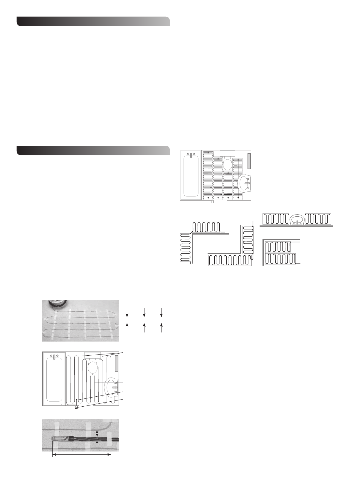
For wood floors the gap between the cable runs should be 82mm (see figure 1).
This gives 120W/m
should be 62mm, this gives 160W/m
runs should be 50mm.
Initially decide on a location for the RCD and controller* then plan the run of
the cold cable to the start of the heating cable and the run of the temperature
probe flying lead, remembering that no cable should cross over or under any
other or the temperature probe which should be positioned as in figure 3.
The cold cable and probe flying lead are 4m long and may be shortened
if necessary.
Cables should be run backwards and forwards between walls or obstructions
(see the example given in figure 2). Cables should not be run under
permanent fixtures. The cables should not get closer to the tiling edge than
50mm and should clear permanent fixtures by the same amount.
If the largest cable in the range is not long enough a second cable can be used
with the two cold cables connected to the controller – black to black to
controller live output and blue to blue to controller neutral output.
* These should not be located in a bathroom or near a sink or cooking facilities in a kitchen.
Figure 1
Figure 2
Figure 3
2
. For concrete/screed floors the gap between cable runs
2
. To give 200W/m2 the gap between cable
Wood
floors
82mm
120W/m
Conserve energy by
avoiding areas (such as
under water cistern) which
are not a normal area for
foot contact.
Heating Cable
Temperature Probe
Controller (must not be
mounted inside bathroom
A groove should be made
in the floor surface to
bring the upper surface of
=
=
the temperature probe and
cable level with the
heating cable.
Concrete/
screed floors
62mm 50mm
2
160W/m
2
200W/m
Mat Layout
These have a fixed output of 160W/m2 and are suitable for concrete/
screed floors.
Initially decide on a location for the RCD and controller* then plan the run of
the cold cable to the start of the heating mat and the run of the temperature
probe flying lead remembering that no cable should run under or over any
other or the temperature probe which should be positioned as in figure 3.
The cold cable and probe flying lead (both 4m in length) may be shortened
as necessary.
Mats should run backwards and forwards between walls or obstructions. The
techniques shown in figures 4 and 5 may prove useful. When cutting the mat
webbing to give direction changes or bypassing of obstacles take care not to
cut or damage the heating cable. Mat runs should be separated by at least
30mm and should not be run under permanent fixtures. The cables within the
mats should not get closer to the tiling edge than 50mm and should clear
permanent fixtures by the same amount. If the longest mat in the range is not
long enough to cover the required area a second mat or cable can be used
with the two cold cables connected to the controller controller – black to black
to controller live output and blue to blue to controller neutral output.
* These should not be located in a bathroom or near a sink or cooking facilities in a kitchen.
Figure 4
When cutting the mat
webbing to give direction
changes or the bypassing
of obstacles take care not
to cut or damage the
heating cable.
Figure 5
Obstacle cut
Empty square
Filled square
Corner cuts Plain wall cut
Flexi-Fast Mat Layout
These give an output of between 133 and 200W/m2 depending on the degree
of stretch (maximum stretch gives 133W/m
Initially decide on a location for the RCD and controller* then plan the run of
the cold cable to the start of the heating mat and the run of the temperature
probe flying lead remembering that no cable should run under or over any
other or the temperature probe which should be positioned as in figure 3.
The cold cable and probe flying lead (both 4m in length) may be shortened
2
as necessary.
Mats should run backwards and forwards between walls or obstructions.
Generally it will be sufficient to pin the mat at the start and finish of each
run if there is a degree of stretch in the mat. The techniques shown in figures
4 and 5 may prove useful. When cutting the mat webbing to give direction
changes or bypassing of obstacles take care not to cut or damage the heating
cable. Mat runs should be separated by at least 30mm and should not be run
under permanent fixtures. The cables within the mats should not get closer to
the tiling edge than 50mm and should clear permanent fixtures by the same
amount. If the longest flexi-fast mat in the range is not long enough to cover
the required area at the required W/m
used with the two cold cables connected to the controller – black to black to
controller live output and blue to blue to controller neutral output.
* These should not be located in a bathroom or near a sink or cooking facilities in a kitchen.
2
).
2
a second flexi-fast mat or cable can be
150mm
Page 4
5. Installation of Cable or Mat 6. Installation of Controller & RCD
Wood Floor
Initially remove any dust and debris from the floor surface and follow the notes on preparing
the surface in section 3. Then check the flexi-fast mat or cable resistance against the figures
given in section 2, also check the temperature probe resistance (approx 110kΩ at 20°C for
RAMSES 714 A and TPT88, 10kΩ at 20°C for TPT1 and TPT44, decreasing with increasing
temperature). If the readings are okay proceed with laying the flexi-fast mat or cable:-
a. Cable.
During the installation wear soft soled shoes and avoid treading on the probe or any
of the cables. Working to the planned layout make grooves for the cold cable and the probe
with flying lead to give the same overall height above floor level as the heating cable then
remove debris. Tape the temperature probe and flying lead as well as the cold cable into their
respective grooves using the tape provided. When positioning the heating cable ensure that
it is well clear of the temperature probe (see figure 3). Tape the cable to the floor according
to the plan developed in section 4 with an 82mm cable spacing as shown in figure 1.
The cable should be taped at every bend and also five times along the runs between bends
as shown in figure 6.
Check the cable and probe resistance and then coat the cables and adjacent floor with a thin
layer of adhesive with the essential flexible additive.
The cable and probe resistance should be checked again after the adhesive has set.
If the cable and probe resistance is okay the adhesive with the essential flexible additive should
now be spread evenly over a section of the floor until the cable is completely covered, then slab
laying or tiling is carried out over this section. The process is repeated section by section until
the floor is completed.
When grouting it is essential to use a flexible additive mixed with the grout. The cable and
probe resistance should be checked again on completion of the grouting.
NOW ALLOW 10 DAYS FOR THE SCREED TO COMPLETELY SET AT A NORMAL ROOM
TEMPERATURE BEFORE COMMISSIONING.
Figure 6
b. Flexi-Fast Mat
During the installation wear soft soled shoes and avoid treading on the probe or any
of the cables. Working to the planned layout make grooves for the cold cable and the probe
with flying lead to give the same overall height above floor level as the heating cable then
remove debris. Tape the temperature probe and flying lead as well as the cold cable into their
respective grooves using duct tape. When positioning the flexi-fast mat ensure that the heating
cable is well clear of the temperature probe (see figure 3). Drill two holes 6mm dia. at least
17mm deep close to the ends of each run of flexi-fast mat. These are to locate the push-fit
plugs supplied. They should engage with each of the two outer runs of webbing within the
flexi-fast mat (not the cable). The start of each run of flexi-fast mat should be placed in position
smooth side down and the plugs pushed home hard trapping the webbing under the heads of
the plugs. The mat should be stretched to close to its maximum length to give 133W/m
two more plugs pushed home into the pre-drilled holes at the end of the run. Cut the webbing
(avoiding damage to the heating cable) to reverse direction or avoid obstacles using the
techniques shown in figures 4 and 5 whilst continuing to fix further runs of the flexi-fast mat.
When reaching the last two or three runs the stretch can be adjusted to use up the complete
cable (count the cable loops on one side of the remaining mat length to do this).
Check the cable and probe resistance and then coat the cables and adjacent floor with a thin
layer of adhesive with the essential flexible additive.
The cable and probe resistance should be checked again after the adhesive has set.
If the cable and probe resistance are okay the adhesive with the essential flexible additive
should now be spread evenly over a section of the floor until the flexi-fast mat is completely
covered, then slab laying or tiling is carried out over this section. The process is repeated section
by section until the floor is completed.
When grouting it is essential to use a flexible additive mixed with the grout. The cable and
probe resistance should be checked again on completion of the grouting.
NOW ALLOW 10 DAYS FOR THE SCREED TO COMPLETELY SET AT A NORMAL ROOM
TEMPERATURE BEFORE COMMISSIONING.
2
and
Concrete or Screed Floor
Initially remove any dust and debris from the floor surface and follow the notes on preparing
the surface in section 3. Then check the flexi-fast mat or cable resistance against the figures
given in section 2, also check the temperature probe resistance (approx 110kΩ at 20°C for
RAMSES 714 A and TPT88, 10kΩ at 20°C for TPT1 and TPT44, decreasing with increasing
temperature). If the readings are okay proceed with laying the flexi-fast mat or cable:-
a. Cable
Proceed as for wood floor (a) except use a cable spacing of 62mm (see figure 1).
b. Mat
During the installation wear soft soled shoes and avoid treading on the probe or any
of the cables. Working to the planned layout make grooves for the cold cable and the probe
with flying lead to give the same overall height above floor level as the heating cable then
remove debris. Tape the temperature probe and flying lead as well as the cold cable into their
respective grooves using duct tape. When positioning the mat ensure that the heating cable is
well clear of the temperature probe (see figure 3). Fix the matting smooth side down using the
three runs of adhesive tape already fixed to it. This is best achieved by removing the backing on
this tape over a short length then fixing the mat down before moving to the next section. Cut
the webbing (avoiding damage to the heating cable) to reverse direction or to avoid obstacles
using the techniques shown in figures 4 and 5.
Check the cable and probe resistance and then coat the cables and adjacent floor with a thin
layer of adhesive with the essential flexible additive.
The cable and probe resistance should be checked again after the adhesive has set.
If these are both okay the adhesive with the essential flexible additive should now be spread
evenly over a section of the floor until the mat is completely covered then slab laying or tiling is
carried out over this section. This process is repeated section by section until the floor is
completed.
When grouting it is essential to use a flexible additive mixed with the grout. The cable and
probe resistance should be checked again on completion of the grouting.
NOW ALLOW 10 DAYS FOR THE SCREED TO COMPLETELY SET AT A NORMAL ROOM
TEMPERATURE BEFORE COMMISSIONING.
c. Flexi-Fast Mat
Proceed as for wood floor (b) except the degree of stretch is low to give 200W/m2.
Note: The 10 year guarantee cover of mats and cables as components is not effective
unless the installation is protected by an RCD.
The installation of the Controller and RCD must be carried out according to their
respective instructions and the installation must comply with the current I.E.E. Wiring
Regulations. If there is any doubt about how to proceed please contact the Helpline
on 020 8450 0515 or a competent professional person.
Fix the controller and RCD in the required positions. We suggest the controller is mounted
around head height for ease of programming. Terminate the incoming supply leads to the RCD
in accordance with its instructions. Connect the RCD output to the incoming supply terminals of
the controller in accordance with its instructions. After measuring and recording the overall
cable resistance the cold cable may now be connected to the output terminals of the controller,
shortening the cold cable as necessary. After measuring and recording the temperature probe
resistance and the approximate room temperature the probe flying lead may now be connected
to the probe terminals on the controller, shortening the flying lead as necessary.
7. Commissioning
Referring to the appropriate instructions turn the RCD on and set the controller to the
maximum temperature in continuous operation. There should be a noticeable change in the
floor surface temperature after one hour with a wood floor and up to five hours with a
concrete floor.
The controller should now be adjusted to a temperature giving the required comfort and the
timing (if incorporated) set as required.
We recommend a temperature setting of 28°C
8. Do’s and Do Not’s
Do not cut the heating cable.
Do not leave surplus matting or cable rolled up under units or fixtures – use the right size.
Do not cross any cables.
Do not switch mat or cable on until 10 days after fitting.
Do not cut or prepare tiles etc on top of the finished area.
Do consult the Helpline or a competent professional person if you are unsure how to proceed.
Do use an approved flexible additive mixed with screed/adhesive.
Do use an approved flexible additive mixed with the grout.
Do cover the area where mats or cables have been laid for protection.
Do keep a record of cable and probe resistance for later referral.
Do keep a drawing of where the mat/cable was laid to enable any future structural work to
proceed without damage.
Do fit an RCD if the installation is not protected by one already. Timeguard does not
guarantee cables or mats where the installation is not RCD protected.
9. Guarantees
Heating Cables, Mats, Flexi-Fast Mats, Temperature Probes
(including flying leads).
It is necessary to retain proof of purchase to validate the guarantee.
In the unlikely event of any of these products becoming faulty due to defective
material or manufacture within 10 years of the date of purchase please contact
Timeguard and it will be replaced free of charge.
This guarantee is subject to the following conditions:a. The cable/mat/flexi-fast mat has been installed and used in full compliance with
the installation instructions 1 – 8 above.
b. The cable/mat/flexi-fast mat has been earthed and protected by an RCD at all times.
c. The cable/mat/flexi-fast mat has been used with a controller supplied by Timeguard.
d. Proof of purchase will be required so keep an invoice detailing the cable/mat/
flexi-fast mat(s) and controller purchased.
e. Accidental damage to the cable/mat/flexi-fast mat during or after installation is not
covered.
The guarantee covers the above components ONLY but NOT installations and
associated floor covering products.
There is no other guarantee, express or implied. No claim can be brought
against the manufacturer or its agents for any consequential damages
whatsoever.
Controllers and RCD’s.
It is necessary to retain proof of purchase to validate the guarantee.
In the unlikely event of any of these products becoming faulty due to defective
material or manufacture within 3 years of the date of purchase please return it to
your supplier with proof of purchase and it will be replaced free of charge.
There is no other guarantee, express or implied. No claim can be brought
against the manufacturer or its agents for any consequential damages
whatsoever.
Helpline & Technical Service Direct Line
Tel: 020 8450 0515 Fax: 020 8450 0635
Email: csc@timeguard.com
Website: www.thermolay.co.uk
Victory Park, 400 Edgware Road, London NW2 6ND
Timeguard Limited
A Group Company
67.058.472
Zerofour – January 2012
 Loading...