

Timeguard FBT4, FBT5 Installation & Operating Instructions Manual
Installation & Operating Instructions
Electronic Boost Timer
& Fused Spur
Model: FBT4 – 2 Hour Boost Timer
Model: FBT5 – 4 Hour Boost Timer

1
1. General Information
These instructions should be read carefully and retained for further
reference and maintenance.
2. Safety
• Before installation or maintenance, ensure the mains supply to the
boost timer is switched off and the circuit supply fuses are removed
or the circuit breaker turned off.
• It is recommended that a qualified electrician is consulted or used for
the installation of this boost timer and install in accordance with the
current IEE wiring and Building Regulations.
• Check that the total load on the circuit including when this boost
timer is fitted does not exceed the rating of the circuit cable,
fuse or circuit breaker.
3. Technical Specifications
• 230V AC 50 Hz
• Fused: Supplied with BS1362 13A Fuse
• Switch Rating: 13A Resistive (3kW)
1000W Incandescent,
Halogen lighting
500W Fluorescent lighting
200W LED lighting
100W Compact Fluorescent lighting
• Contact Type: Normally Open
• Minimum Depth of Wall Box: 25mm
• Boost Times: FBT4 ¼, ½, 1, 2 hours
FBT5 1, 2, 3, 4 hours
• Operating Temperature: 0°C to +40°C
• CE Approved
• Dimensions (H x W x D): 85mm x 85mm x 31mm
Note: Not suitable for use with Discharge Lighting.
2
3
4. Installation
• Ensure the mains supply is switched off and the circuit supply
fuses are removed or the circuit breaker turned off.
• Connect the incoming 230V 50Hz supply and outgoing load
cables to the relevant terminals ensuring correct polarity
is observed and that all bare conductors are sleeved
(see section 5. Connection Diagram).
• A front cable exit cut-out is provided with a pre-installed
removable cover.
• If the front exiting cable cut-out is required:
1. Undo the 2 fixing screws and remove the blanking plate
(you can discard the blanking plate at this stage but keep
the 2 fixing screws).
2. Remove the cable grip from the accessory pack.
3. Using the 2 fixing screws previously removed from the blanking
plate, secure the load cable to the unit.
• Finally secure the unit to the back box with the fixing screws
provided, forming the cables during installation to avoid any
entrapment and cable damage.
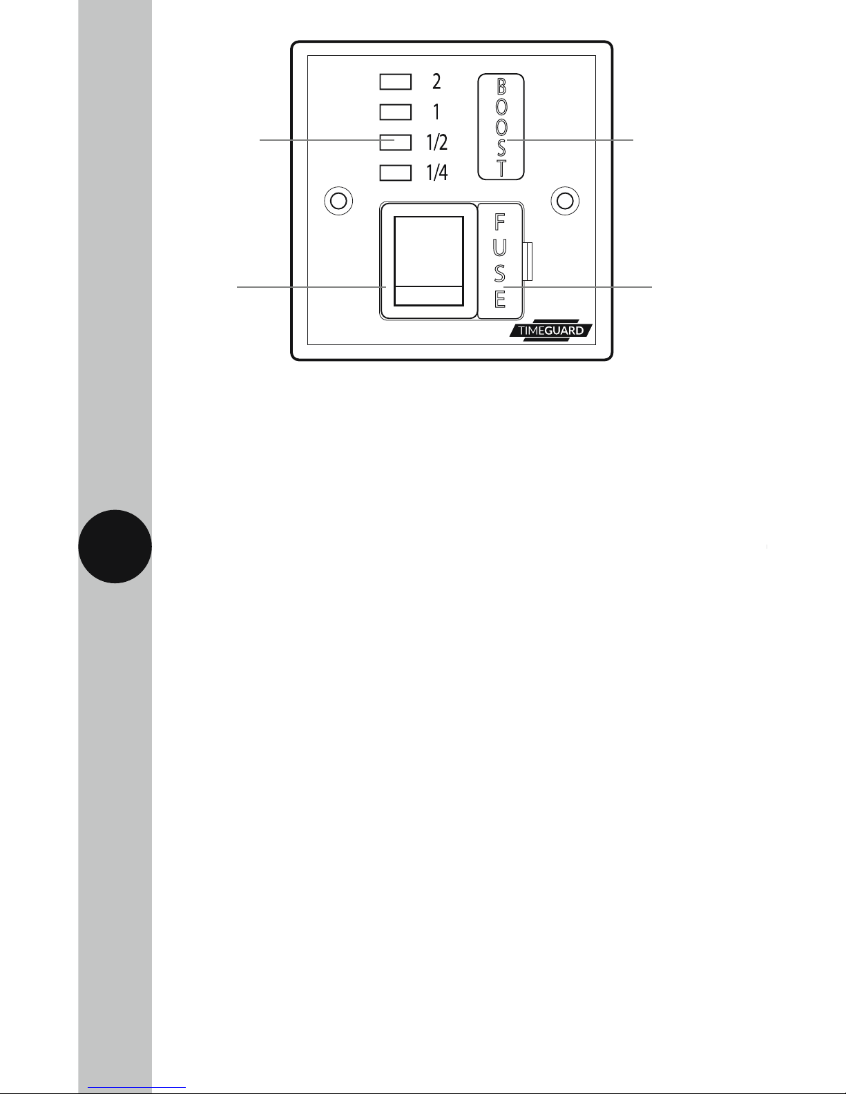
Boost time
indicator LEDs
Double
pole switch
BS 1362
(1"x
1
/4")
fuse
Boost button
 Loading...