

Page 1
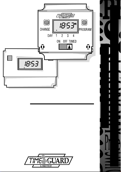
INSTALLATION & OPERATING
ON
INSTRUCTIONS
Panel
MEU11 (24 Hour) MEU17 (7 Day)
(Giving Panel Mount Capability)
EMU11 (24 Hour) EMU17 (7 Day)
MASTER
Timer Modules
Without Housing
With Housing
Page 2
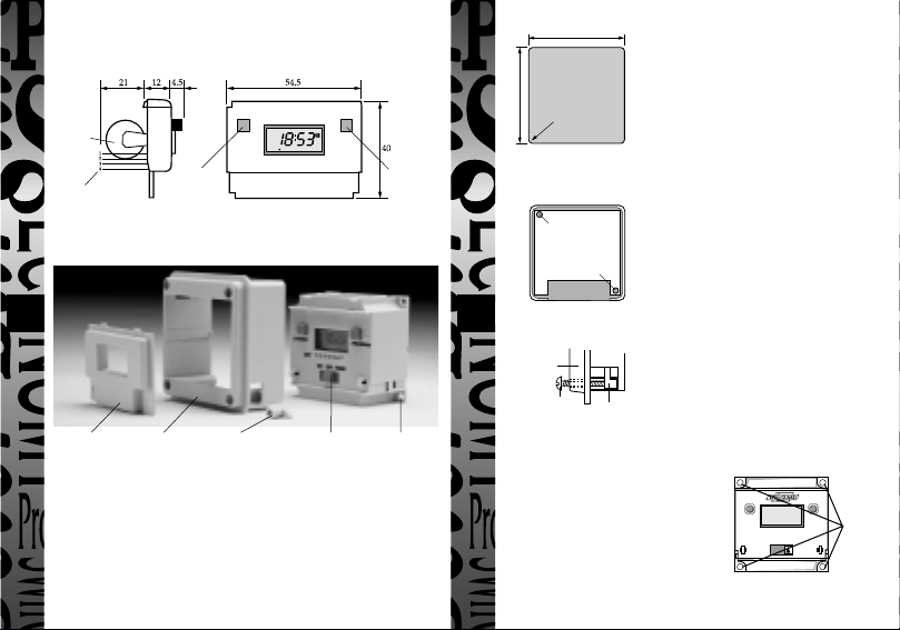
1. Physical Arrangements & Installation Instructions
MEU 11 & MEU 17
Metal
Hydride
Battery
Change
Pin Header
button
Engineering drawing can be supplied on request
EMU 11 & EMU 17
Tamper proof
Contents
1 EMU11 (24 hour) or EMU17 (7 day)
1 Panel mount bezel
1 Tamper proof cover
4 Surface mount stand offs (length 10mm)
2 Panel mount bolts
2 Self-tapping screws (No. 4 x 5/8 in) for panel mount bolts
2 Self-tapping screws (No.6 x 3/8 in) for attaching bezel to EMU11/17
cover
Bezel for panel
mounting
Panel mount
bolts
Slide switch allowing
continuous ON or
OFF or programmed
operation
Figure 1
Programme
button
Surface
mount fixing
Fig 2
67mm
67mm
R 3.5mm
Fig 3
Use No. 6 x 3/8in selftapping screws to fully
secure bezel to EMU11/17
(fixed from rear)
Fig 4
Bezel
No. 4 x 5/8in selftapping screw
Surface Mounting
The EMU11/17 without bezel can be surface
mounted using the 4 securing holes as shown
in figure 5. The unit can be stood off from the
mounting surface by 10mm using the 4 spacers
if required. Screws are not provided and it
must be remembered that if used in this way
the EMU11/17 must be installed within a
housing or cubicle to prevent access to the
mains terminations.
Installation - Panel Mounting
For panel mounting (in panels up to 7.0mm thick
with the cut-out as shown in figure 2) the
EMU11/17 should be snapped into the bezel
supplied and secured in place by the use of the 2
No. 6 x 3/8in self-tapping screws provided as
shown in figure 3.
When selecting a position for the unit it should be
born in mind that a clearance behind the front
panel surface of 26.0mm is required over the full
area of the panel cut-out.
The unit is designed to be mounted from the front
of the panel by the following procedure:
a. Insert the 2 bolts provided in the locations
shown in figure 4.
b. Then insert the 2 No. 4 x 5/8 in self-tapping
screws into the bolts and engage thread.
c. Make connections to the unit by wires
terminated in a Molex 4 way 7720 or similar
connector from behind the panel.
d. Insert the EMU11/17 complete with bezel into
the panel and tighten up the 2 No. 4 selftapping screws. The ears on the bolts will
Bolt
rotate under the tightening action to clamp the
unit to the panel.
4 fixing
holes for
surface
mounting
Fig 5
Page 3
2. Specifications
MEU11 & EMU11
●
4 ON/OFF programmes
●
Easy 2 button programming
●
Change/Override until next programme
●
Rechargeable Metal Hydride battery back-up with 1000 hours reserve
●
Requires only an external diode, resistor and relay to switch mains
●
Temperature range 0° to 55°C
Operation
The programme button advances programme steps and the change
button the hours and minutes which flash. Time of day is set first
and is updated during the programming period. Programmes 1 to 4
follow. If, during programming, no button is pressed over a period
of one minute then the display will revert to normal operation. In
normal operation, pressing the change button changes the output
until the next programme step.
MEU17 & EMU17
●
6 ON/OFF programmes, daily, weekly, weekend or weekday options
●
Easy 2 button programming
●
Change/Override until next programme
●
Rechargeable Metal Hydride battery back-up with 1000 hours reserve
●
Requires only an external resistor, diode and relay to switch mains
●
Temperature range 0° to 55°C
Operation
The programme button advances programme steps and the change
button then updates the item selected. Day/days of week is first to
be programmed followed by hours and minutes. The 6 ON/OFF
programmes then follow, each in the sequence day/days, hours
and minutes. If, during programming, no button is pressed over a
period of one minute then the display will revert to normal
operation. In normal operation, pressing the change button changes
the output until the next programme step.
4 5 6321
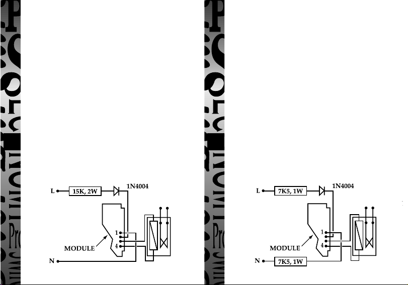
Single Resistor PSU (MEU11 & MEU17 only) Two Resistor PSU - gives Optimum EMC Performance
(MEU11 & MEU17 only)
Fig 7Fig 6
Page 4

All Types
Connections
Pin 1: Common.
Pin 2: Positive battery charge plus relay current. Min 0.50 mA (No relay).
Pin 3: Relay connection.
Pin 4: Output & relay connection. NPN open connector. Max 10 mA, 47 V
A Molex 7720 4 way connector or similar is recommended.
MEU11 and MEU17 - Typical Usage
The examples in figs 6, 7 and 8 show the module driving a Shrack 48V
relay with power derived from the mains. Type RP330048 or RP331048
(Changeover contracts). In these configurations the relay pulls in at 47V
and is held at above 24V with mains voltages down to 200V.
EMU11 and EMU17 - Typical Usage
In this case the circuit in fig 6 can be used with a 10K, 3W resistor in place of the
15K, 2W resistor shown and a 1.3W zener must be connected between pins 1
and 2 of the module. The circuit in fig 7 can be used with two 5K1, 1.5W
resistors in place of the 7K5, 1W resistors shown and a 1.3W zener must be
connected between pins 1 and 2 of the module. The circuit in fig 8 can be used
with a 330nF, X 250V ac capacitor instead of the 220nf capacitor shown and a
1.3W zener must be connected between pins 1 and 2 of the module.
In all cases the zener is 47V and its cathode is connected to module pin 2.
Capacitor PSU (MEU11 & MEU17 only)
Fig 8
It is possible to operate these modules from other voltages.
Please contact Technical Service on 020 8450 0515 for advice.
3. EMU11 & MEU11 Programming Instructions
Change Button
sets Hours and
Minute times and
self cancelling
override
Easy view 24
hour digital
clock/timer
display
Battery
This product has a factory fitted rechargeable battery. If the time controller is left with
its mains power switched off for more than 1 month the display may go blank. In this
case switch mains on, wait 30 minutes, and apply reset - see 1 before programming.
Programming
Only two setting buttons are required, Change and Program. In normal use the Change
button is used to switch ON or OFF, overriding the timeswitch until the next
programmed OFF or ON time. During programming the Change button is used to set
the hours and minutes. The Program button is only used when setting or adjusting the
clock time or the 4 programmed ON/OFF times, although it can also be used to review
the ON/OFF times once they have been set. Each time the Program button is pressed the
display will flash either the hours or minutes in turn, starting with the clock then the first
ON time, first OFF time, second ON time etc. Wherever the hours or minutes are
flashing they may be set using the Change button. Once set the Program button is
pressed again to proceed to the next stage.
Normal Operating Mode
In normal operation the PanelMaster will display the
correct time with the colon flashing. The output
status will be shown by either ON or OFF on the display.
1 To Reset Display
To clear programmes from memory and reset the time controller press and hold
down both buttons until the display goes blank.
Release buttons and display will fill with its complete
range of characters and then clear to show clock and
hour digit flashing.
You are now in the clock setting mode
at the beginning of the programme sequence
Programme Button
used to select the
clock time and the 4
ON/OFF
programme times
and to review them
once set
Output Status
showing unit
either ON or OFF
1 2 3 4
1 2 3 4
Page 5

ON
Programming sequence
....
Setting clock
Programme 1 ON
Programme 1 OFF
Programme 2 ON
Programme 2 OFF
Note: Button pauses greater than 1 minute during programming will result in
automatic return to the operating mode.
2 Setting Clock (after reset)
i Hour Setting - Press the <Change> button to advance
the hour setting.Note: For rapid hour selections press
and hold down <Change> button.
ii Minute Setting - Press the <Program> button once to
select the minutes - display shows clock symbol
and minute digits flashing. Press the <Change>
7
button to advance the minutes setting. Note: For rapid
minute selection press and hold down <Change>
button. (Note: 16 hrs shown as example of hrs set)
iii Press <Program> button once - clock is now set and
display shows ready for the first ON programme time
with ON and hours digits flashing.
3. To Set Programme ON/OFF Times
(after clock setting)
Programme 1 ON time
i Press <Change> button to advance the
ii Press <Program> button once to select minute time -
display shows minute digits and ON flashing. Press
<Change> button to advance minute setting.
(Note: 16 hrs shown as example of hours set).
:
:
:
:
:
......
:
hour setting.
➔
Programme 3 ON
Programme 3 OFF
Programme 4 ON
Programme 4 OFF
Operating Mode
1 2 3 4
1 2 3 4
1 2 3 4
1 2 3 4
iii Press <Program> button once - the first ON time is
now set and display shows ready for the first OFF
programme time.
iv Now set the hrs and minutes as before.
v Repeat steps i to iv to set the remainder of the 3 ON/OFF times as required.
Note: Any unused ON/OFF programme should be skipped until the display
shows normal operating mode. Do not programme ‘0’s into unused
programmes.
IMPORTANT After setting a clock time which falls within a programmed ON
period, the unit will not switch ON. Use the Change button to switch unit ON.
After this the unit will operate normally to the programmes set.
4. Programme Review
To fast review the set programmes or for quick exit to normal operating mode press and hold the <Program> button.
5. Initiating Programme Mode
This can be initiated any time during the normal operating mode. Press
8
<Program> button and the Clock symbol, hrs and minutes symbols on the
display will flash - this is review mode. If any change to programmes is
required press <Change> button to initiate programme mode and then follow
steps 2 and 3.
6. Cancelling Programmes
Any ON/OFF programme can be cancelled by clearing its ON and OFF time.
Follow step 5 and when into the ON or OFF programme to be cancelled press
the <Change> button until the hour digits show --:
then press the <Program> button to clear the
programme. The display will show the hour
and minute digits and ON or OFF flashing.
Self Cancelling Override
To change the output status from ON to OFF or vice versa during normal operation
press the <Change> button. The output status will change and indicate override is in
operation by flashing.
1 2 3 4
ON
1 2 3 4
Page 6

ON
4. EMU17 & MEU17 Programming Instructions
Change Button
sets Day(s), Hours
and Minute times
and self cancelling
override
Easy view 24
hour digital
clock/timer
display
Battery
This product has a factory fitted rechargeable battery. If the time controller is left with
its mains power switched off for more than 1 month the display may go blank. In
this case switch mains on, wait 30 mins, and apply reset - see 1 before programming.
Programming
This is a seven day (weekly) timeswitch which has six programmes, each of which
can be block programmed to work on all of the five weekdays, both weekend days,
or all 7seven days (24 hour operation). Programmes can also be designated to
operate on individual days.
Only two setting buttons are required, Change and Program. In normal use the
Change button is used to switch ON or OFF, overriding the timeswitch until the
next programmed OFF or ON time. During programming the Change button is
used to set the hours, minutes and days. The Program button is only used when
setting or adjusting the clock time and day or the 6 programmed ON/OFF times
and days, although it can also be used to review the ON/OFF times and days once
they have been set. Each time the Program button is pressed the display will flash
either the days, hours or minutes in turn, starting with the clock then the first ON
time and day(s), first OFF time, second ON time and day(s) etc. Wherever the
days, hours or minutes are flashing they may be set using the Change button. Once
set the Program button is pressed again to proceed to the next stage.
Normal Operating Mode
In normal operation the PanelMaster will display the
correct day and its time with the colon flashing. The output
status will be shown by either ON or OFF on the display.
Programme Button
used to select the
clock time and the 6
ON/OFF programme
times and to review
them once set
Output Status
showing unit
either ON or OFF
Day indicator
1 = Monday
7 = Sunday
OFF
1 2 3 4 5 6 7
1 To Reset Display
To clear programmes from memory and reset the time controller press and hold
down both buttons until the display goes blank. Release buttons and display will
fill with its complete range of characters and then clear
to show clock and day 1 symbol flashing.
You are now in the clock setting mode
at the beginning of the programme sequence
Programming sequence
Note: Button pauses greater than 1 minute during programming will result in
automatic return to the operating mode.
2 Setting Clock (after reset)
i Day Setting - Press <Change> button to advance to the day required.
Day 1 = Monday and Day 7 = Sunday.
ii Hour Setting - Press the <Program> button once to
select the hour - display shows clock symbol and
the hrs
digit flashing.
Press the <Change> button to advance
the hour setting.Note: For rapid hour selections press
and hold down <Change> button.
iii Minute Setting - Press the <Program> button once to
select the minutes - display shows with clock symbol
and minute digits flashing. Press the <Change>
button to advance the minutes setting. Note: For rapid
minute selection press and hold down <Change>
button. (Note: 16 hrs shown as example of hrs set)
iv Press <Program> button once - clock is now set and
display shows ready for the first ON programme time.
Setting clock
Programme 1 ON
Programme 1 OFF
Programme 2 ON
Programme 2 OFF
Programme 3 ON
Programme 3 OFF
......
....
➔
Programme 4 ON
:
:
Programme 4 OFF
:
Programme 5 ON
:
Programme 5 OFF
:
Programme 6 ON
:
:
Programme 6 OFF
:
Operating Mode
1 2 3 4 5 6 7
1 2 3 4 5 6 7
1 2 3 4 5 6 7
ON
1 2 3 4 5 6 7
Page 7

HELPLINE
020-8450-8944
For a product brochure please contact:
Timeguard Ltd.
Victory Park, 400 Edgware Road,
London NW2 6ND
Tel: 020 8452 1112
or email csc@timeguard.com
Designed and manufactured in the U.K. 67-057-97 (2)
 Loading...