

Page 1
INSTALLATION & OPERATING
PROGRAM
DAY 1 2 3 4 5 6 7
CHANGE
ON OFF TIMED
ON
PROGRAM
DAY 1 2 3 4
CHANGE
ON OFF TIMED
ON
INSTRUCTIONS
Panel
MASTER
Models
EL11 (24 hour)
EL17 (7 day)
Page 2
PROGRAM
DAY 1 2 3 4
CHANGE
ON OFF TIMED
ON
PROGRAM
DAY 1 2 3 4 5 6 7
CHANGE
ON OFF TIMED
ON
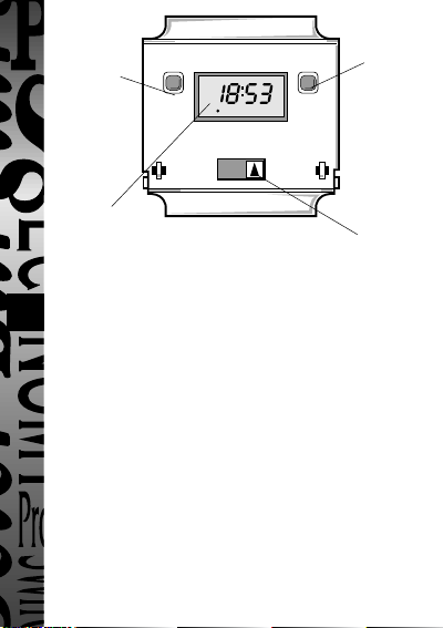
Figure 1
N
NOC
NC
L
Override button
(also used in
conjunction with the
programme button
to programme clock
and times/days for
ON periods
24 hour clock
display
Slide switch provides
Contents
1 EL11 (24 hour) or EL17 (7 day)
1 Panel mount bezel
1 Tamper proof cover
4 Surface mount stand offs (length 10mm)
2 Panel mount bolts
2 Self-tapping screws (No. 4 x 5/8 in) for panel mount bolts
2 Self-tapping screws (No.6 x 3/8 in) for attaching bezel to EL11/17
General
The EL11 (24 hour) or EL17 (7 day) is primarily a panel mounted timeswitch
rated at 240V, 16A resistive at T40. It can also be surface mounted within
cubicles if required.
The contacts are single pole change over and are fully voltage free. The front of
the unit is shown in figure 1. The rear of the unit showing wiring connections
and the internal circuit is shown in figure 2.
Connections are made to the EL11/17 by 1/4 in receptacles. The unit can be
made tamper proof by wiring the cover supplied in place which still leaves the
display visible.
Programme button
used to programme
clock and times/days
for ON periods
continuous ON,
continuous OFF or
normal programme
operation
Page 3
PROGRAM
DAY 1 2 3 4
CHANGE
ON OFF TIMED
ON
Installation - Panel Mounting
N
NOC
NC
L
For panel mounting (in panels up to 7.0mm thick with the cut-out as shown in
figure 3) the EL11/17 should be snapped into the bezel supplied and secured
in place by the use of the 2 No. 6 x 3/8in self-tapping screws provided as
shown in figure 4.
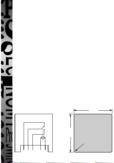
When selecting a position for the unit it should be born in mind that a
clearance behind the front panel surface of 26.0mm is required over the full
area of the panel cut-out.
The unit is designed to be mounted from the front of the panel by the
following procedure:
a. Insert the 2 bolts provided in the locations shown in figure 5.
b. Then insert the 2 No. 4 x 5/8 in self-tapping screws into the bolts and
engage thread.
c. Make connections to the unit by wires terminated in 1/4 in receptacles
from behind the panel. Ensure that the wiring is adequate for the load to
be carried.
d. Insert the EL11/17 complete with bezel into the panel and tighten up the
2 No. 4 self-tapping screws. The ears on the bolts will rotate under the
tightening action to clamp the unit to the panel.
67mm
Figure 2
67mm
R 3.5mm
Figure 3
Page 4
PROGRAM
DAY 1 2 3 4
CHANGE
ON OFF TIMED
ON
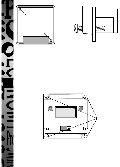
Use No. 6 x 3/8in selftapping screws to fully
secure bezel to EL11/17
(fixed from rear)
Bezel
No. 4 x 5/8in selftapping screw
Figure 4
Surface Mounting
The EL11/17 without bezel can be surface mounted using the 4 securing holes
as shown in figure 6. The unit can be stood off from the mounting surface by
10mm using the 4 spacers if required. Screws are not provided and it must be
remembered that if used in this way the EL11/17 must be installed within a
housing or cubicle to prevent access to the mains terminations.
Figure 6
On/Off/Timed Slide Switch
The three position slide switch allows continuously ON, continuously OFF or
normal programmed operation.
Figure 5
Bolt
4 fixing holes
for surface
mounting
Page 5

PROGRAM
DAY 1 2 3 4
CHANGE
ON OFF TIMED
ON
EL11 Programming Instructions
Change Button
sets Hours and
Minute times and
self cancelling
override
Easy view 24
hour digital
clock/timer
display
Battery
This product has a factory fitted rechargeable battery. If the time controller is left with
its mains power switched off for more than 1 month the display may go blank. In this
case switch mains on, wait 30 minutes, and apply reset - see 1 before programming.
Programming
Only two setting buttons are provided <Change> and <Program>. During the
programme mode the <Change> button is used to set the hour and minute times.
Holding this button down achieves rapid selection of the hr and minute times. It is
also used for changing the output status during normal operation. The <Program>
button is used to select the clock time and 4 ON/OFF programmes and to review
them once set. Holding this button down achieves rapid selection of the next
programmes or can be used as a quick exit from programme mode or programme
review.
Normal Operating Mode
In normal operation the PanelMaster will display the
correct time with the colon flashing. The output
status will be shown by either ON or OFF on the display.
1 To Reset Display
To clear programmes from memory and reset the time controller press and hold
down both buttons until the display goes blank.
Release buttons and display will fill with its complete
range of characters and then clear to show clock and
hour digit flashing.
You are now in the clock setting mode
at the beginning of the programme sequence
Programme Button
used to select the
clock time and the 4
ON/OFF
programme times
and to review them
once set
Output Status
showing unit
either ON or OFF
OFF
1 2 3 4
1 2 3 4
Page 6

Programming sequence
....
......
➔
Programme 3 ON
:
:
Programme 3 OFF
:
Programme 4 ON
:
Programme 4 OFF
:
:
Operating Mode
hour setting.
Setting clock
Programme 1 ON
Programme 1 OFF
Programme 2 ON
Programme 2 OFF
Note: Button pauses greater than 1 minute during programming will result in
automatic return to the operating mode.
2 Setting Clock (after reset)
i Hour Setting - Press the <Change> button to advance
the hour setting.Note: For rapid hour selections press
and hold down <Change> button.
ii Minute Setting - Press the <Program> button once to
select the minutes - display shows clock symbol
and minute digits flashing. Press the <Change>
54321
button to advance the minutes setting. Note: For rapid
minute selection press and hold down <Change>
button. (Note: 16 hrs shown as example of hrs set)
iii Press <Program> button once - clock is now set and
display shows ready for the first ON programme time
with ON and hours digits flashing.
3. To Set Programme ON/OFF Times
(after clock setting)
Programme 1 ON time
i Press <Change> button to advance the
1 2 3 4
1 2 3 4
ON
1 2 3 4
ii Press <Program> button once to select minute time -
display shows minute digits and ON flashing. Press
<Change> button to advance minute setting.
(Note: 16 hrs shown as example of hours set).
ON
1 2 3 4
Page 7

iii Press <Program> button once - the first ON time is
now set and display shows ready for the first OFF
programme time.
iv Now set the hrs and minutes as before.
v Repeat steps i to iv to set the remainder of the 3 ON/OFF times as required.
Note: Any unused ON/OFF programme should be skipped until the display
shows normal operating mode. Do not programme ‘0’s into unused
programmes.
IMPORTANT After setting a clock time which falls within a programmed ON
period, the unit will not switch ON. Use the override facility to switch unit ON.
After this the unit will operate normally to the programmes set.
4. Programme Review
To fast review the set programmes or for quick exit to normal operating mode press and hold the <Program> button.
5. Initiating Programme Mode
This can be initiated any time during the normal operating mode. Press
6
<Program> button and the Clock symbol, hrs and minutes symbols on the
display will flash - this is review mode. If any change to programmes is
required press <Change> button to initiate programme mode and then follow
steps 2 and 3.
6. Cancelling Programmes
Any ON/OFF programme can be cancelled by clearing its ON and OFF time.
Follow step 5 and when into the ON or OFF programme to be cancelled press
the <Change> button until the hour digits show -- :
then press the <Program> button to clear the
programme. The display will show the hour
and minute digits and ON or OFF flashing.
Self Cancelling Override
To change the output status from ON to OFF or vice versa during normal operation
press the <Change> button. The output status will change and indicate override is in
operation by flashing.
1 2 3 4
1 2 3 4
OFF
ON
Page 8

PROGRAM
DAY 1 2 3 4 5 6 7
CHANGE
ON OFF TIMED
ON
EL17 Programming Instructions
PROGRAM
DAY 1 2 3 4 5 6 7
CHANGE
ON OFF TIMED
ON
PROGRAM
DAY 1 2 3 4
CHANGE
ON OFF TIMED
ON
Change Button
sets Day(s), Hours
and Minute times
and self cancelling
override
Easy view 24
hour digital
clock/timer
display
Battery
This product has a factory fitted rechargeable battery. If the time controller is left with
its mains power switched off for more than 1 month the display may go blank. In
this case switch mains on, wait 30 mins, and apply reset - see 1 before programming.
Programming
Only two setting buttons are provided <Change> and <Program>. During the
programme mode the <Change> button is used to set days and the hour and
minute times. Holding this button down achieves rapid selection of the day and
the hour and minute times. During normal operation it is used for changing the
output status. The <Program> button is used to select the clock time and 6
ON/OFF programmes and to review them once set. Holding this button down
achieves rapid selection of the next programmes or can be used as a quick exit
from programme mode.
Normal Operating Mode
In normal operation the PanelMaster will display the
correct day and its time with the colon flashing. The output
status will be shown by either ON or OFF on the display.
1 To Reset Display
To clear programmes from memory and reset the time controller press and hold
down both buttons until the display goes blank.
Release buttons and display will fill with its complete
range of characters and then clear to show clock and
day 1 symbol flashing.
You are now in the clock setting mode
at the beginning of the programme sequence
Programme Button
used to select the
clock time and the 6
ON/OFF
programme times
and to review them
once set
Output Status
showing unit
either ON or OFF
Day indicator
1 = Monday
7 = Sunday
OFF
1 2 3 4 5 6 7
1 2 3 4 5 6 7
Page 9

Programming sequence
PROGRAM
DAY 1 2 3 4 5 6 7
CHANGE
ON OFF TIMED
ON
PROGRAM
DAY 1 2 3 4
CHANGE
ON OFF TIMED
ON
....
......
➔
Programme 4 ON
:
:
Programme 4 OFF
:
Programme 5 ON
:
Programme 5 OFF
:
Programme 6 ON
:
:
Programme 6 OFF
:
Operating Mode
Setting clock
Programme 1 ON
Programme 1 OFF
Programme 2 ON
Programme 2 OFF
Programme 3 ON
Programme 3 OFF
Note: Button pauses greater than 1 minute during programming will result in
automatic return to the operating mode.
2 Setting Clock (after reset)
i Day Setting - Press <Change> button to advance to the day required.
Day 1 = Monday and Day 7 = Sunday.
ii Hour Setting - Press the <Program>
button once to select the hour - display
shows clock symbol and the hrs
digit flashing.
Press the <Change> button to advance
the hour setting.Note: For rapid hour selections press
and hold down <Change> button.
iii Minute Setting - Press the <Program> button once to
select the minutes - display shows with clock symbol
and minute digits flashing. Press the <Change>
button to advance the minutes setting. Note: For rapid
minute selection press and hold down <Change>
button. (Note: 16 hrs shown as example of hrs set)
iv Press <Program> button once - clock is now set and
display shows ready for the first ON programme time.
3. To Set Programme ON/OFF Times (after clock setting)
Programme 1 ON time
i Press <Change> button to advance the day flag to the required day(s) settings
which are:
1 2 3 4 5 6 7
1 2 3 4 5 6 7
ON
1 2 3 4 5 6 7
Page 10

1234567
PROGRAM
DAY 1 2 3 4 5 6 7
CHANGE
ON OFF TIMED
ON
PROGRAM
DAY 1 2 3 4
CHANGE
ON OFF TIMED
ON
●●●●●
●●●●●●●
●
ii
Once day option selected press <Program>
button once to select hour time - display
shows hour digits and ON flashing. Press
<Change> button to advance hour setting.
(Note: Monday shown as an example of days set).
iii Press <Program> button once to select minute time -
display shows minute digits and ON flashing. Press
<Change> button to advance minute setting.
(Note: 16 hrs shown as example of hours set).
iv Press <Program> button once - the first ON time is
now set and display shows ready for the first OFF
programme time.
v Now set the hrs and minutes as before.
The day(s) selected remains the same.
vi Repeat steps i to v to set the remainder of the 5 ON/OFF times as required. Note:
Any unused ON/OFF programme should be skipped until the display shows
normal operating mode. Do not programme ‘0’s into unused programmes.
IMPORTANT After setting a clock time which falls within a programmed ON
period, the unit will not switch ON. Use the override facility to switch unit ON.
After this the unit will operate normally to the programmes set.
4. Programme Review
To fast review the set programmes or for quick exit to normal operating mode press and hold the <Program> button.
5. Initiating Programme Mode
This can be initiated any time during the normal operating mode. Press
<Program> button and the Clock symbol, day flag, hrs and minutes symbols
on the display will flash - this is review mode. If any change to programmes is
required press <Change> button to initiate programme mode and then follow
steps 2 and 3.
●●
=
5 days (Weekdays)
=
2 days (Weekend)
=
7 days (Everyday)
=
Individual days
Mo Tu We Th Fr
Sa Su
Mo Tu We Th Fr Sa Su
Starting with Monday through to Sunday
●
1 2 3 4 5 6 7
●
1 2 3 4 5 6 7
●
1 2 3 4 5 6 7
ON
ON
OFF
Page 11

6. Cancelling Programmes
PROGRAM
DAY 1 2 3 4 5 6 7
CHANGE
ON OFF TIMED
ON
PROGRAM
DAY 1 2 3 4
CHANGE
ON OFF TIMED
ON
Any ON/OFF programme can be cancelled by clearing its ON and OFF time.
Follow step 5 and when into the ON or OFF programme to be cancelled press
the <Change> button until the hour digits show -- :
then press the <Program> button to clear the
programme. The display will show the hour and
minute digits and ON or OFF flashing.
(Note: Monday shown as an example of days set).
Self Cancelling Override
To change the output status from ON to OFF or vice versa during normal operation
press the <Change> button. The output status will change and indicate override is in
operation by flashing.
Specifications
1. A fully CE marked product conforming to BS EN 60730-2-7 for function and
safety as a control to be incorporated in other equipment.
2. Complies with EMC standards EN50081-1 for emission and EN50082-1 for
immunity as a control to be incorporated in other equipment.
10987
3. Contacts: Silver Cadmium Oxide. Single pole change over.
4. Permissible Loads: 16A Resistive
For other loads refer to Technical Service on 020 8450 0515
*This load with power factor correction capacitors is not recommended for
normally closed contacts.
5. Panel Cut Out: 67mm square with 2.5mm radius corners.
6. Battery Back-up: 1000 hours by factory fitted rechargeable battery.
7. Operating abmient temperature: -10°C to 40°C. Upper limit can be
8. Operating Voltage: 220 - 240V AC 50Hz.
6A At 0.4 power factor inductive
10A Filament lamps
*500W Fluorescent lighting with or without power factor
correction capacitors (4µF per 65W tube)
1h.p. Motor
increased for loads less than 16A - refer to
Technical Service.
ON
●
1 2 3 4 5 6 7
 Loading...