

Page 1
Installation & Operating Instructions
Emergency Assist
Alarm Kit – Single Zone
Model: EASZKN
Page 2

1
2
1. General Information
These instructions should be read carefully and retained for further
reference and maintenance.
2. Safety
• Before installation or maintenance, ensure the mains supply to the
alarm system is switched off and the circuit supply fuses are removed
or the circuit breaker turned off. Remove all power sources when
wiring any part of the system.
• It is recommended that a qualified electrician is consulted or used
for the installation of this alarm system and install in accordance
with the current IEE wiring and Building Regulations.
• Check that the total load on the circuit including when this alarm
system is fitted does not exceed the rating of the circuit cable,
fuse or circuit breaker.
• None of the units in the system should be subject to dripping or
splashing liquids.
• To clean use a clean dry cloth only. Do not use and liquid cleaners.
3. Technical Specifications
• Control Unit Supply Voltage: 230V AC 50Hz
• Zone Components Supply Voltage: SELV (24V)
• This Control Unit is of class I Construction and must be earthed
• The individual components are class III and must not be earthed
• Maximum pull force on Pull Cord: 200N
• Pull Cord Length: 2m (including 2 red bangles)
• Reset button marking: Visually and with Braille
• Intensity of sounders:
Control Unit: 80dB at 30cm (continuous)
Over-Door Unit: 80dB at 30cm (continuous)
• LED Indicators:
Control Unit: Green ‘Power ON’, Blue ‘Alarm’
Over-Door Light: Blue illuminates during alarm only
Reset Unit: Blue illuminates during alarm only
Pull Cord Unit: Blue illuminates during alarm only
Angular Coverage of Indicator: 180° on Over-Door Unit
Page 3
2
• Operating Temperature: +5°C to 40°C
• IP Rating: Intended for indoor use only
• CE Compliant
• Dimensions:
Control Unit:
H=85mm, W=145mm, D=33mm
Over-Door Unit:
H=85mm, W=85mm, D=32mm
Reset Unit:
H=85mm, W=85mm, D=29mm
Pull Cord Unit:
H=85mm, W=85mm, D=30mm
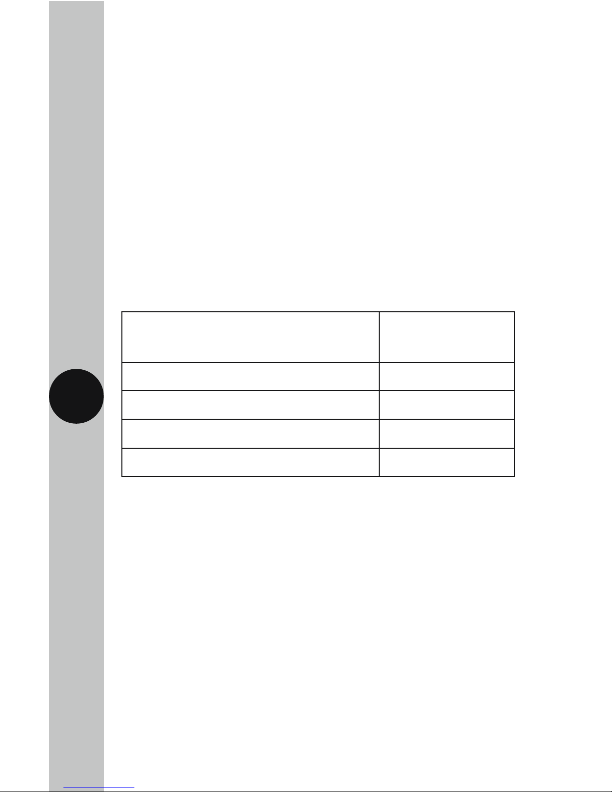
Wall box minimum depth requirements – All Components:
Component
Minimum Depth
Requirement
Single Zone Control Unit 26mm
Over-Door Light 16mm
Reset Unit 16mm
Pull Cord Unit 16mm
• Features inside moulded dry lining back boxes may cause interference
with the product, the diagram below illustrates where these may occur.
• In the event of interference, the problem feature should be carefully
trimmed with a blade or cutters. To ensure correct installation an
MK or Centaur deep dry line box should be used.
4. Contents
• 1x Single Zone Control Unit
• 1x Over-Door Light
• 1x Reset Unit
• 1x Pull Cord Unit
• 1x W.C. Sticker
• 1x Instruction Manual
Page 4

3
5. Installation
Important:
• Connect the Safety Extra Low Voltage (SELV) wiring first.
• Connect the mains wiring last.
• When installing the 26mm wall box for the control unit, choose
the fixing holes to ensure clearance between the screw heads
and the rear of the control unit.
• An isolation switch should be installed to enable the power to be
switched ON and OFF for maintenance purposes. (Fuse 3A BS1362).
• For permanently connected apparatus either provided with an all-pole
mains switch or an all-pole circuit breaker, the installation shall be
carried out in accordance with all applicable installation rules.
• Where an all-pole mains switch or an all-pole circuit breaker is used
as the disconnect device, it shall have contact separation of at least
3mm in each pole and shall disconnect all poles simultaneously.
5.1 Single Zone Control Unit:
Mains Wiring (Important): This should be sited (following the
recommendations of the BS8300 code of practice to meet
the needs of disabled people) where it can best attract the
attention of an appropriate person or member of staff. An example
of this is near a reception desk in view of a receptionist.
• Having located the installation site, install a flush or surface
mount double gang wall box (see wall box minimum depth
requirements for details).
• Pass the 230V AC 50Hz mains supply cable (1mm
2
twin and earth)
into the wall box.
• Terminate the cables into the Control Unit marked ‘L’ and ‘N’
ensuring correct polarity is observed and that all bare conductors
are sleeved (See section 6. Mains Voltage Wiring).
• Connect the incoming earth wire as follows;
NOTE: This is a class 1 apparatus if a metal box is used and therefore
the earth wire MUST be connected to the earth terminal of the metal
box itself. If a plastic box is used, connect the earth wire to the Earth
connector marked on the Control Unit.
Page 5

4
5
Safety Extra Low Voltage Wiring (SELV)
Important: Ensure that the low voltage wiring is kept well away from
mains wiring. The low voltage wiring must be tied to each other using
the tie wrap provided to overcome clearances and to be held secure
from creepage distances if any wiring becomes detached.
• Pass the extra low voltage two core cable into the wall box and
connect to the terminals marked ‘OUT’ on the control unit
(see section 7. Extra Low Voltage Wiring). The system is not
polarity conscious.
• The interconnections should be made with suitable low voltage
cable such as bell wire or alarm cable with copper conductors
of at least 7/0.2mm.
• Fit the Control Unit to the wall box and secure using the two
fixing screws provided.
5.2 Over-Door Light:
Important: This should be sited to attract appropriate personnel
to the area where assistance is required. An example of this is above
the cubicle door of the toilet.
• Having located the site, install a flush or surface mount single gang
wall box (see wall box minimum depth requirements for details).
• Pass the extra low voltage two core cable from the Control Unit
through the wall box and connect to the terminals marked ‘IN’
(See section 7. Extra Low Voltage Wiring).
• Bring a further extra low voltage two core cable into the wall box
and connect to the terminals marked ‘OUT’.
• Fit the Over-Door Light to the wall box and secure using the fixing
screws provided.
• Fix the W.C. sticker to cubicle door.
Page 6

5
5.3 Reset Unit:
Important: The BS8300 recommends that this should be sited on a wall
such that for a toilet it can be reached from the W.C. and a wheelchair.
The recommended height is between 750 and 1200mm above the floor
and horizontally it must not be mounted closer than 350mm to any corner.
• Having located the site, install a flush or surface mount single gang
wall box (see wall box minimum depth requirements for details).
• Pass the extra low voltage two core cable from the Over-Door Light
through the wall box and connect to the terminals marked ‘IN’
(See section 7. Extra Low Voltage Wiring).
• Bring a further extra low voltage two core cable into the wall box
and connect to the terminals marked ‘OUT’.
• Fit the Reset Unit to the wall box and secure using the fixing
screws provided.
5.4 Pull Cord Unit:
Important: The BS8300 recommends that this should be sited on the ceiling
such that for a toilet it can be operated from the W.C. and an adjacent area.
The lower handle should be set 100mm above the floor (knot and trim off
excess cord) and the upper handle should be set between 800 and 1000mm
above the floor (knot the cord at the required height).
• Having located the site, install a flush or surface mount single gang
wall box (see wall box minimum depth requirements for details).
• Pass the extra low voltage two core cable from the Reset Unit through
the wall box and connect to the terminals on the Pull Cord Unit
(See section 7. Extra Low Voltage Wiring).
• Fit the Pull Cord Unit to the wall box and secure using the fixing
screws provided.
Page 7

6
6. Mains Voltage Wiring:
230V 50Hz Mains Supply
Live Supply (Brown or Red) to L
Neutral Supply (Blue or Black) to N
Earth Connection (Green/Yellow) to
LNE
230V AC 50Hz
MAINS SUPPLY
Earth
Live
Neutral
Page 8

7
7. Extra Low Voltage Wiring:
Single Zone Control Unit (Rear)
Over-D oor Light
Reset Unit
Pull Cord Unit
Out
Out In
NE L
Out In
WARNING
Do not
connect to
mains supply!
Mains Rating
Information
Connector
for incoming
mains supply
Control
Board
2 Wire Extra
Low Voltage
Fixing
Holes
Fixing
Holes
Fixing
Holes
Components must be wired in the order shown above
Page 9

8
9
8. Commissioning:
• Switch on the 230V AC 50Hz mains supply to the Control Unit and
check that the ‘on’ indicator (green) is illuminated. The Alarm indicator
(blue) should be off.
• Test the alarm system by pulling the Pull Cord Unit, the alarm will
trigger the sounders on the Over-Door Light as well as the Single Zone
Control Unit. The Pull Cord Unit, Reset Unit and the Over-Door Unit will
all emit a static blue light during the period that the alarm is triggered.
• Press the Reset button on the Control Unit to end the alarm.
Test the alarm once again by pulling the Pull Cord Unit, this time
use the Reset Unit to end the alarm.
9. Operation:
• When the pull cord, mounted adjacent to the W.C. is pulled,
the blue LED on the Pull Cord Unit will be activated until
the system is reset, assuring the disabled person in distress
that the system has been activated.
• At the reset unit inside the cubicle, the light and sounder
will simultaneously trigger and remain on continuously;
which will further reassure the person in distress.
• The sounder and the light on the Over-Door Unit outside the cubicle
will remain on until the alarm system has been reset.
• At the Control Unit the blue alarm light and the sounder
are activated continuously.
• Either the Over-door Unit or the Control Unit will attract the attention
of an appropriate person either directly or indirectly and that person will
note the system is in alarm, press the reset button at the Control Unit
clearing the alarm and will then investigate the cubicle in question.
• At any time if the difficulty is resolved the person in distress can clear
the alarm by pressing the reset button in the cubicle.
Page 10

9
10. Typical Single Zone System
Single Zone Control Unit
2-wire
2-wire
2-wire
Fused Spur
(not supplied)
Pull Cord Unit
Reset Unit
Over Door Unit
Page 11

10
11. Troubleshooting
Problem
• The Green (Supply ON)
LED on the Control Unit
is OFF.
Solution
The mains supply is not connected,
check the mains wiring.
The mains is switched OFF, switch
back ON.
• The system will
not reset.
Disconnect the mains supply from the
control unit, and then reconnect the mains
supply. If the alarm has not reset, disconnect
the mains supply from the control unit
and remove the pull cord unit completely.
Reconnect the mains supply back to the
control unit. If the system has now reset,
a new pull cord would be required.
• Pull Cord does not
initiate an alarm.
The Pull Cord is not connected or inserted
properly, check the connections to the Pull
Cord unit.
3 Year Guarantee
In the unlikely event of this product becoming faulty due to defective
material or manufacture within 3 years of the date of purchase, please
return it to your supplier in the first year with proof of purchase and it
will be replaced free of charge. For the second and third years or any
difficulty in the first year telephone the helpline on 020 8450 0515.
Note: A proof of purchase is required in all cases. For all eligible
replacements (where agreed by Timeguard) the customer is responsible
for all shipping/postage charges outside of the UK. All shipping costs
are to be paid in advance before a replacement is sent out.
Page 12

Zerofour – May 2018
67.058.634 (Issue 1)
Timeguard Limited.
Victory Park, 400 Edgware Road,
London NW2 6ND
Sales Office: 020 8452 1112
or email csc@timeguard.com
For a product brochure please contact:
HELPLINE
020 8450 0515
or email helpline@timeguard.com
www.timeguard.com
Qualified Customer Support Coordinators will be online
to assist in resolving your query.
If you experience problems, do not immediately
return the unit to the store.
Telephone the Timeguard Customer Helpline;
 Loading...