

Page 1

INSTALLATION & OPERATING INSTRUCTIONS
EMERGENCY
ASSIST ALARM
Models covered:
Single Zone Plastic Control Unit
Single Zone Stainless Steel Control Unit
Plastic Reset Unit
Stainless Steel Reset Unit
Plastic Over-Door Unit
Stainless Steel Over-Door Unit
Pull Cord Unit
Four Zone Plastic Control Unit
Four Zone Stainless Steel Control Unit
Single Zone Plastic System Kit
Single Zone Stainless Steel System Kit
Page 2

1
1. Models Covered
Components
Single Zone Plastic Control Unit EACP1
(with battery back up EACP1PR)
Single Zone Stainless Steel Control Unit EASSCP1
(with battery back up EASSCP1PR)
Plastic Reset Unit EARB1
Stainless Steel Reset Unit EASSRB1
Plastic Over-Door Unit EADF1
Stainless Steel Over-Door Unit EASSDF1
Pull Cord Unit EAPC1
Four Zone Plastic Control Unit EACP4
(with battery back up EACP4PR)
Four Zone Stainless Steel Control Unit EASSCP4
(with battery back up EASSCP4PR)
Kits
Single Zone Plastic System Kit EASZK
(with battery back up EASZPRK)
Single Zone Stainless Steel System Kit EASSSZK
(with battery back up EASSSZPRK)
Both of which comprise of components from the above list
Page 3
2
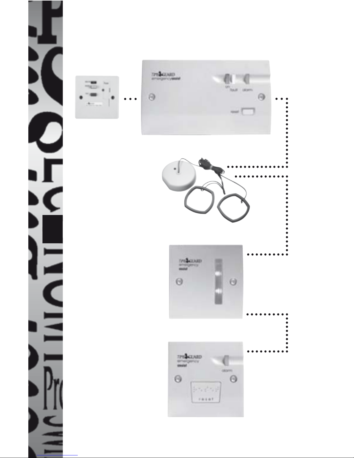
Typical Single Zone System
(Available as EASZK)
Pull Cord Unit
Over Door Unit
Reset Unit
Single Zone Control Unit
2-wire
2-wire
2-wire
Fused Spur
(not supplied)
Page 4
3
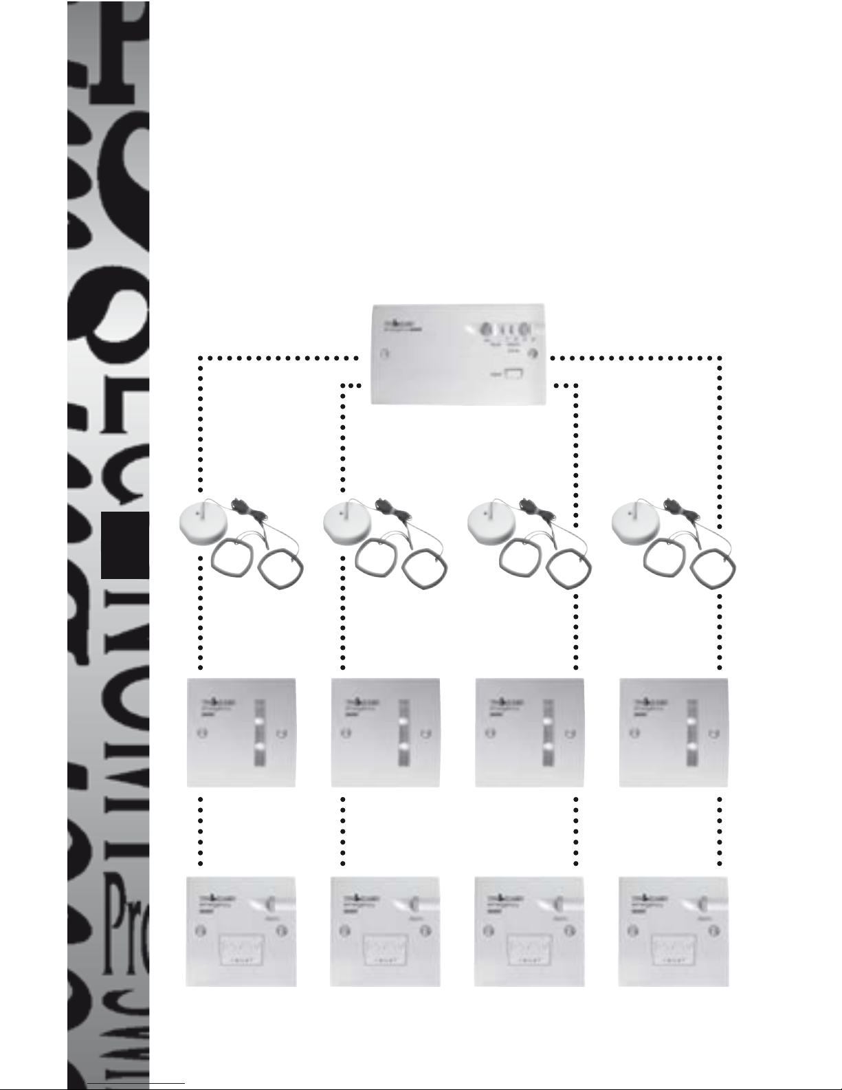
Typical Four Zone System
There are no four zone kits, but two to four zones can be
accommodated by using any of the four zone Control Units
in combination with the appropriate number of Reset Units,
Over-Door Units and Pull Cord Units. There are no adverse
effects if any of the four zone control units input connections
are left open.
Four Zone Control Unit
Pull Cord Unit
Over Door Unit
Reset Unit
2-wire
2-wire
2-wire
Page 5

4
2. Introduction
The basic system consists of a Control Unit (which is powered
by AC mains supply) connected by an extra low voltage 2wire link to a Pull Cord Unit which is in turn connected to an
Over-Door Unit by another extra low voltage 2-wire link. The
Over-Door Unit is then connected to a Reset Unit by a further
extra low voltage 2-wire link.
When the pull cord, mounted adjacent to the W.C., is pulled,
the red L.E.D. on the Pull Cord Unit is activated until the system
is reset, assuring the disabled person in distress that the
system has been activated. The sounder and the light on the
Over-Door Unit outside the cubicle, are activated intermittently.
At the Reset Unit inside the cubicle, the light and sounder are
activated intermittently and will both be further reassuring the
person in distress. At the Control Unit the alarm light and the
sounder are activated continuously.
Either the Over-Door Unit or the Control Unit will attract the
attention of an appropriate person either directly or indirectly
and that person will note the zone in alarm, press the reset
button at the Control Unit clearing the alarm and then
investigate the toilet cubicle in question.
Note: Reset button at the Control Unit can be disabled by
moving the reset selection switch to the OFF position.
At any time if the difficulty is resolved the person in distress
can clear the alarm by pressing the reset button in the cubicle.
3. Installation
• Important: This system must be installed and maintained by
a suitably qualified person. Connect the Extra Low Voltage
wiring first. Connect Mains wiring last. See mains ratings
in diagram. Mains supply must come from a fused spur and
Page 6

5
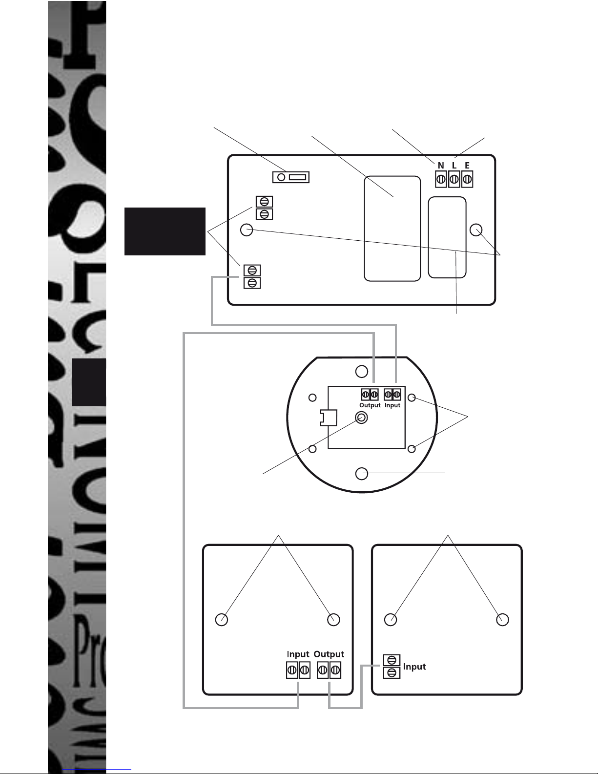
External
Alarm Buzzer
Output
Control Unit (Rear)
Over-Door Unit (Rear)
Pull Cord Unit (Backplate)
Reset Unit (Rear)
Reset
Selection
Connector for
incoming mains
supply
Transformer
Battery Holder
(Back-up PR
versions only)
Fixing
Holes
Fixing Holes
Cover Fixing HolesPull Cord Hole
Fixing Holes Fixing Holes
WARNING
Do not
connect to
mains supply!
Wiring and Fixing Holes
Final page gives expanded view of this diagram.
MUST be switched off at all times while installation is in
progress
• The installation shall be carried out in accordance with all
applicable installation rules.
• None of the units in the system should be subject to
dripping or splashing liquids.
• When using the Control Unit with a 25mm deep box choose
the fixing holes to ensure clearance between the screw
heads and the rear of the control unit.
Mains rating
information
Page 7

6
3.1. Control Unit
This should be sited (following the recommendations
of BS8300) where it can best attract the attention of an
appropriate person/member of staff. An example of this is near
a reception desk in view of a receptionist.
Having located the site, install a flush or surface mount double
gang wall box at least 25mm deep.
Bring the mains supply cable (1mm
2
twin and earth) into the
box and connect to the terminals on the Control Unit marked
‘L’ and ‘N’ (see diagram). Connect the incoming wiring as
instructed below.
Mains Wiring
Important: All mains wiring should be provided in accordance
with the relevant national wiring rules
Bring the mains supply cable (1mm
2
TFE) into the box and
connect the Live and Neutral wires to the terminals on the
Control Unit marked ‘L’ and ‘N’ respectively.(see diagram)
Ensure the lengths of wires inside the connectors are prepared
correctly. Connection should be made firmly after all strands
are entered into the terminals.). Connect the incoming earth
wire as instructed below
NOTE: This is a class 1 apparatus if a metal box
is used and therefore the earth wire MUST be
connected to the earth terminal of the metal
box itself. If a plastic box is used, connect the
earth wire to the Earth connector marked
on the Control board.
On the stainless steel version, connect the
earth wire to the Earth connector on the
Control board. The metal box will be earthed
via the stainless steel screws provided.
Page 8

7
Extra Low Voltage Wiring
Important: Ensure that low voltage wiring are kept well away
from mains wiring. The low voltage wiring must be tied to each
other using the tie wrap provided to overcome clearances and
creepage distances if any wire becomes detached.
Bring the extra low voltage two core cable into the wall box
and connect to the terminals marked output (see diagram). The
system is not polarity conscious. Fix the Control Unit to the wall
box using the screws provided. Insert battery into battery holder
Connections are as above diagram for a single zone system. The
four zone system is similar except that the four zone Control
Unit has 4 outputs, each one being used will have a Pull Cord
Unit, an Over-Door Unit and a Reset Unit connected in the same
way as the single zone system. Any unused outputs should be
left unconnected. The interconnections should be made with
two core cable of at least 7/0.2mm copper conductors (bell flex
is suitable).
Finally, if reset capability is not required at the Control Unit,
move the reset selection switch to the OFF position.
Page 9

8
3.2. Pull Cord Unit
BS8300 (code of practice for the design of buildings and their
approaches to meet the needs of disabled people) recommends
that this should be sited on the ceiling such that for a toilet it
can be operated from the W.C. and an adjacent floor area. The
lower handle should be set 100mm above the floor (knot and
trim off any excess cord) and the upper handle should be set
between 800 and 1000mm above the floor (knot the cord at
required height).
Hold the unit backplate in position on the ceiling and mark
through the fixing holes on the unit backplate and drill and
plug (if necessary) holes suitable for four No 6 screws.
Bring the extra low voltage two core cable from the Control
Unit through the backplate and connect to the terminals
marked input (see diagram).
Bring a further extra low voltage two core cable through the
backplate and connect to the terminals marked output.
Fit the cover to the backplate and fix with the two screws
provided. Attach the two handles to the pull cord as described
at the beginning of this section.
Page 10

9
3.4. Reset Unit
BS8300 recommends that this should be sited on a wall
such that for a toilet it can be reached from the W.C. and a
wheelchair. The recommended height is between 750 and
1200mm above the floor and horizontally it must not be
mounted closer than 350mm to any corner.
Having located the site, install a flush or surface mount single
gang wall box at least 25mm deep.
Bring the extra low voltage two core cable from the Over-Door
Unit into the wall box and connect it to the terminals marked
input (see diagram).
Fix the Reset Unit to the wall box using the screws provided.
3.3. Over-Door Unit
This should be sited to attract appropriate personnel to the
area where assistance is required. An example of this is above
the toilet cubicle door.
Having located the site, install a flush or surface mount single
gang wall box at least 25mm deep.
Bring the extra low voltage two core cable from the Pull Cord
Unit into the wall box and connect to the terminals marked
input (see diagram).
Bring a further extra low voltage two core cable into the wall
box and connect to the terminals marked output.
Fix the Over-Door Unit to the wall box using the screws
provided.
Fix the W.C sticker to the cubicle door.
Page 11

10
4. Battery
A battery is provided with the following control units and kits
- EACP1PR, EASSCP1PR, EACP4PR or EASSCP4PR and cannot
be fitted to other types.
To fit the battery remove it from the holder and turn it round
and offer it up to the connector and after correct polarity is
ensured press the battery into the connector.
The battery takes 48 hours to get to full charge from when first
connected to the control unit and mains voltage applied to the
L and N terminals.
An illustration of full reserve capability is as follows:
Single zone system Typically 4 days on standby with
2 hours continuous alarm.
Four zone system 1 day on standby with 30 minutes
continuous alarm (1 zone only).
Caution. Danger of explosion if battery is
incorrectly connected. Replace only with same
type of NIMH rechargeable battery.
Important. Ensure battery is inserted with correct
polarity. Do not force battery onto contacts.
Battery Disposal
When battery has reached end of useful life insulate terminals
and consult your local authority about disposal.
DO NOT DISPOSE OF IN FIRE.
Page 12

11
5. Commissioning
Switch on the mains supply to the Control Unit and check the
left hand ‘Supply On’ indicator (green) is illuminated. The ‘Fault’
(yellow) and ‘Alarm’ (blue) indicators should be off.
If the Fault indicator is illuminated this almost certainly
indicates that there is an open or short circuit in the extra low
voltage wiring. Assuming the Fault indicator is off pull the pull
cord and the system should behave as described in the second
paragraph of section 2.
Having observed this to be the case press the Reset button on
the Control Unit to end the alarm. Pull the pull cord again and
verify each unit is performing correctly then press the Reset
button on the Reset Unit to end the alarm.
6. Diagnostics
Warning : Switch off mains supply before removing
the front cover or dismantling the control unit.
Remove all power source including battery when
wiring any part of the system.
The following possible faults and solutions are for guidelines
only. If in doubt contact the Timeguard Helpline on
020 8450 0515
Page 13
12
Symptoms Possible fault Possible
Solution
Green LED on
Control Unit is OFF
Mains supply not
connected
Mains switch is off
Check Mains wiring
Switch on mains
supply
Yellow LED on
Control Unit is ON
Some units in the
system are not
properly connected
Battery is not fully
charged
Checks the 2 wire
link in all units are
properly secured in
the connectors.
If system is running
on backup battery,
check that the
battery is fully
charged
Blue LED on
Control Unit is
continuously ON
and cannot be
reset
2 wire link is
shorting
Battery is too low
Check there is no
short circuit in any
unit
Check the 2 wires
are not touching
Switch on mains
supply to charge
battery
Alarm cannot be
reset from Control
Unit
Reset selector in
the OFF position
Move Reset
selector to the ON
position
Pull Cord does not
initiate an alarm
Pull Cord unit is
not connected
Cord is not properly
inserted
Check connections
to the Pull Cord
unit
See description
above
Page 14

13
3 Year Guarantee
In the unlikely event of this product becoming faulty due to
defective material or manufacture within 3 years of the date
of purchase, please return it to your supplier in the first year
with proof of purchase and it will be replaced free of charge.
For the second and third years or any difficulty in the first year
telephone the helpline on 020 8450 0515.
7. Specifications
Control Unit Supply voltage: 230V (+10%, -15%) 50Hz
Operating temperature: +5 to 40°C
Reserve battery: Metal Hydride (rechargeable)
PP3, 9Volt
Alarm Output: DC voltage through 470 ohm
resistor. (Do not connect to
mains voltage source)
Maximum pull force
on pull cord: 200N
Reset button marking: Visually and with Braille
Intensity of sounders: Control Unit and Reset Units
65dB at 30 cm
Over-Door Unit 78dB at 30 cm
Sound and light are intermittent
except Control Unit
Angular coverage of indicator:
180°on Over-Door Unit:
EC directives: Conforms to 73/23/EEC
and 89/336/EEC
Dimensions: plastic (stainless steel)
Control Unit 145 x 85 x 33, (145 x 85 x 35) mm
Pull cord Unit 82 diameter x 20 mm
Overdoor Unit 85 x 85 x 24, (85 x 85 x 25) mm
Reset Unit 85 x 85 x 12, (85 x 85 x 13) mm
Page 15
14
External
Alarm Buzzer
Output
Control Unit (Rear)
Over-Door Unit (Rear)
Pull Cord Unit (Backplate)
Reset Unit (Rear)
Reset
Selection
Connector for
incoming mains
supply
Transformer
Battery Holder
(Back-up PR
versions only)
Fixing
Holes
Fixing Holes
Cover Fixing HolesPull Cord Hole
Fixing Holes Fixing Holes
WARNING
Do not
connect to
mains supply!
Installation Wiring and Fixing Holes
Mains rating
information
Page 16

For a product brochure please contact:
Timeguard Ltd.
Victory Park, 400 Edgware Road,
London NW2 6ND
020-8452-1112
or email csc@timeguard.com
HELPLINE
020-8450-0515
67.058.192
Iss 1
 Loading...