

Page 1
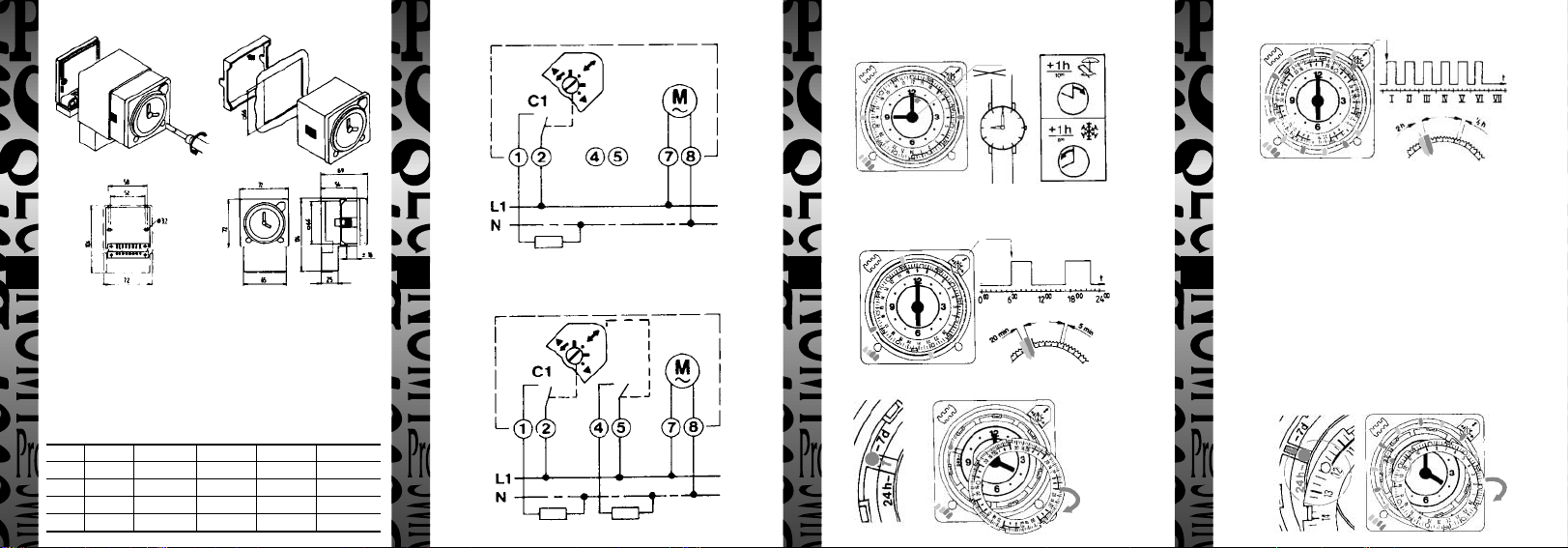
1 Fixing Instructions
3 Circuit Diagrams - E269H & E289H
5 Set Clock
Turn the hands of the clock either clockwise or anticlockwise to the correct time.
9.00
21.00
8 7 Day Programme
1
0
2 Surface Mounting
Lift the transparent cover off and remove the two screws.
Pull the clock body and then the terminal cover from the base.
Mount the base and connect from the diagram.
Flush Mounting
Cut panel opening 66 x 66mm, remove switch from base as above connect from
diagram. Mount on panel using bracket and two knurled screws provided.
Type Dials Power Reserve Switch Period Min Switching Contact Rating
E269H 24hr/7 day - 5 min/30 min 20 min/2hr 20(12)A
E269G 24hr/7 day - 5 min/30 min 20 min/2hr 2 x 20(12)A
E289H 24hr/7 day 150hr 5 min/30 min 20 min/2hr 20(12)A
E289G 24hr/7 day 150hr 5 min/30 min 20 min/2hr 2 x 20(12)A
2 431
4 Circuit Diagrams - E269G & E289G
6 24 Hour Operation
SET SWITCHING TIME - lift off transparent cover and insert the switching
riders to the required position using red for ON and blue for OFF.
1
1
0
7 24 Hour ➔ 7 Day Programme
9 7 Day Operation
1 Lift off transparent cover and the outer ring to expose the yellow and green
circumfrential bands around the clock face. The yellow refers to 7 day
movement,
2 Turn the clock hand either clockwise or anticlockwise to line up the slots
between the green and yellow bands.
3 Slide the silver pin to the yellow band.
4 Replace the outer ring in reverse locating the silver pin into any of the
recesses provided on the ring. The slots on the timing will also engage into
the raised edges provided.
5 You may align the days to suit, i.e. I = Monday, II = Tuesday etc.
6 SET SWITCHING TIME - Insert the switching riders to the required
position using red for ON and blue for OFF.
10 7 Day ➔ 24 Hour Programme
Page 2
HELPLINE
020-8450-0515
For a product brochure please contact:
Timeguard Ltd.
Victory Park, 400 Edgware Road,
London NW2 6ND
Tel: 020 8452 1112
or email csc@timeguard.com
Designed and manufactured in the U.K. 67-056-65 [3]
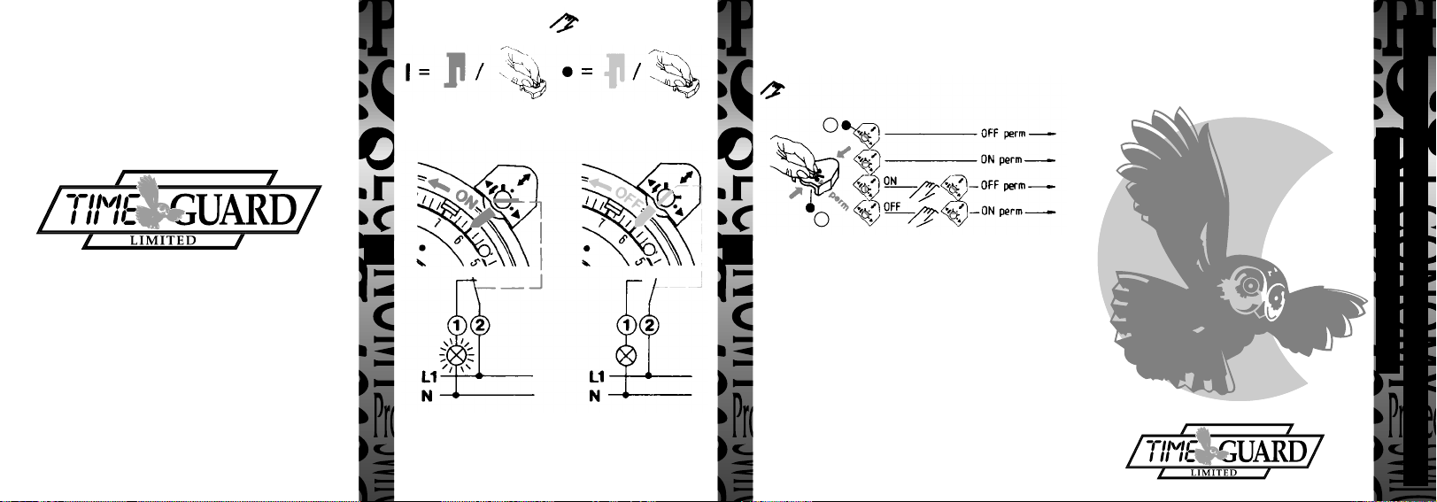
11 Programme Auto/ Manual 12 Manual Control (Override)
The manual control is automatically annuled by the following counteracting
command of the automatic program sequence.
Permanent ON/OFF
3.43.236 (Red) 3.43.237 (Blue)
1
2
65
13 Permanent Control ON/OFF
Set the hand lever to “Perm” = permanent control; turning the control axis 1 in
direction of arrow, the required permanent control ON and OFF can now be
adjusted.
Turning the hand lever to “Auto” = Automatic control, the permanent control is
terminated. The actual switch position is maintained until the next counteracting
command of the automatic program sequence is triggered. An immediate
correction can be carried out by means of the manual control (override control)
Replace transparent cover.
Conforms to directives: 73/23/EEC and 89/336/EEC.
20 AMP ELECTRONIC
INSTALLATION & OPERATING
24HR/7 DAY TIME
CONTROLLER
Cat No.
E269H/E269G - Synchronous
E289H/E289G - Quartz Reserve
INSTRUCTIONS
 Loading...