

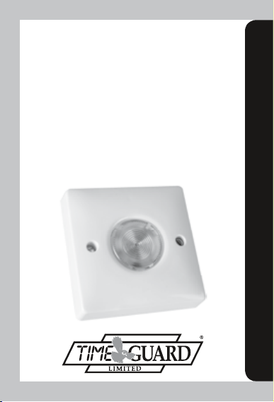
Page 1
2 Wire Electronic
Time Delay Switch
Cat No. DS1
2 Wire Slave Switch
Cat No. DSS
3 Wire Electronic
Time Delay Switch
Cat No. DS2
Installation & Operating Instructions
Page 2
DS1/DSS – Instructions for
Installation and Use
If you have a DS2 please refer to separate instructions
on page 10.
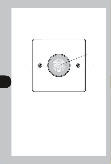
Tough flame
retardant
polycarbonate
plate fits a
standard
single gang
wall box
16mm deep.
Illuminated
push button.
Optional
push-in
screw covers
supplied
1 2
Fig 1 – Front of DS1 and DSS
1. General.
The DS1 is a time delay switch with an illuminated push button,
which replaces a standard single gang plate switch on a box
16mm deep. The illumination guides the user to the push button and
once this is pressed the lights under control are switched on for a
period from approximately 10 seconds to approximately 10 minutes
adjustable by internal potentiometer.
For situations requiring two-way and intermediate switching DSS’s can
be used in conjunction with a single DS1. Section 5 shows how these
can be used in retrofit without wiring modifications and section 2b
shows how they should be wired in new installations.
Page 3
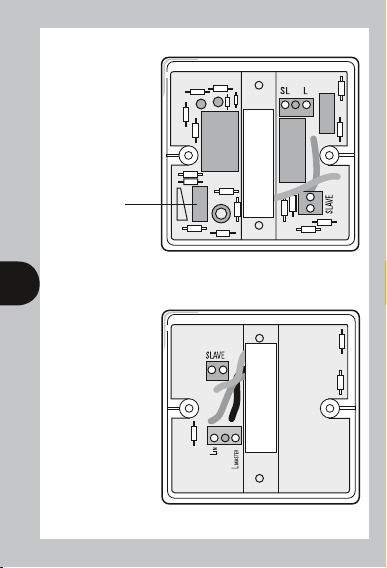
Delay time
adjuster –
centre scale gives
approximately
5 minutes
(linear scale).
Fig 2a – Rear of DS1
2 3
Fig 2b – Rear of DSS
Page 4

2a. Installation (Replacement of
Single ON/OFF Switches Only).
FOR INSTALLATION OF DS1 & DSS’s IN 2 WAY AND
INTERMEDIATE SWITCHING CONFIGURATIONS –
SEE SECTION 5.
IF IN DOUBT CONSULT AN ELECTRICIAN.
SWITCH OFF MAINS ELECTRICITY.
Set the delay time adjuster on the DS1 to minimum (fully anticlockwise – see fig 2a) to enable initial testing during commissioning.
Remove the existing light switch and transfer the two wires to the DS1
connecting them to terminals L and SL in either position. If two wires
were connected to either terminal on the original switch they must be
kept together and connected to either L or SL on the DS1.
Do not disturb any earthing wire connected to the wallbox terminal.
Ensure both terminals are tight before screwing the two plate fixing
screws supplied home sufficiently to locate the DS1 securely to the
3 4
wall box. Turn ON the mains supply.
2b. New Installation of a DS1
and Up to 10 DSS’s.
In a new installation the DS1 and DSS’s can be wired to give control
of a single lamp load by any of the switches.
This is shown in fig 3.
Fig 3
Page 5

If only one DSS is required then connect the mains supply live (L) to
LIN on the DSS and leave the SLAVE connection formerly going to the
second DSS open circuit.
Further DSS’s can be added by copying the circuit connections
shown in Fig 3 between the two DSS’s. The LIN of the second DSS
is connected to LMASTER of the third and LIN of the third to
L (mains supply live) and so on for further DSS’s.
3. Commissioning.
Press the push button and the light(s) under control should come ON
for approximately 10 seconds. During this time the neon behind the
push button switches OFF. If the lamps under control are fluorescent
they will not switch ON immediately and the light intensity may be
reduced initially. If there are DSS’s installed as well repeat this test at
each switch.
Having established that the DS1 and any DSS’s are working correctly
the mains supply should be turned OFF and the two fixing screws
removed from the unit. The DS1 can then be pulled away from the
4 5
wall to enable access to the delay time adjuster (see fig 2a). The delay
time can then be set to the required level and the DS1 fixed to the wall
using the two fixing screws. The push-in screw covers can now
be fitted if required.
The mains supply should be turned ON and the push button pressed
to ensure the delay time is correct.
4. Operation.
Whenever light is required press the closest push button and the
light(s) under control will remain ON for the set delay time.
5. Replacing 2 Way and
Intermediate Switches.
This involves wire identification and tracing. Switch installation should
be left to a competent electrician who will be able to relate the circuit
diagrams shown in figs 4 to 11 to the practical installation.
Page 6

There are two main ways of achieving 2 way switching – Strapping
Cable and Remote Live Access. The circuits for these are shown in
figs 4 and 5. They are shown with a single intermediate switch
giving 3 way switching.
Further intermediate switches can be added.
In keeping with BS schematic
code wires shown in direct
cross over (i.e. +) are not
connected electrically.
5 6
Fig 4 – Strapping Cable & One Intermediate Switch
Fig 5 – Remote Live Access & One Intermediate Switch
Page 7

A DS1 and two DSS’s can be used to replace these switches for both
wiring systems to give time delayed momentary switching at all
three switch locations. The DS1 should not be located at a former
intermediate switch location. The circuits for both wiring systems
with the replacement switches are shown in figs 6 and 7. No wiring
alterations are required but to establish which wires are connected
to which terminals the wires must be identified and traced. An in-line
connector is required for the Strapping Cable System to provide
continuity for the SL connection.
6 7
Fig 6 – Replacement Delay Switches fitted to circuit shown in fig. 4
In keeping with BS schematic code wires shown in direct cross over
(i.e. +) are not connected electrically.
Fig 7 – Replacement Delay Switches fitted to circuit shown in fig. 5
Page 8

Further DSS’s can be added to replace any further intermediate
switches in the system.
If there are no intermediate switches (2 way switching) the before and
after connections for both systems are shown in figs 8 to 11. Note
that an in-line connector is required for the Strapping Cable System to
provide continuity for the SL connection.
Fig 8 – 2 Way Switching – Strapping Cable
7 8
Fig 9 – 2 Way Switching – Remote Live Access
Page 9

Fig 10 – Replacement Delay Switches fitted to circuit shown in fig. 8
In keeping with BS schematic code wires shown in direct cross over
(i.e. +) are not connected electrically.
8
Fig 11 – Replacement Delay Switches fitted to circuit shown in fig. 9
Page 10

6. Specifications – DS1.
i Conforms to Directives: 73/23/EEC & 89/336/EEC
ii Permissible Loads: Filament lamps – 1.5kW
Low voltage – 20 to 200W, Resistive 2kW
Not suitable for fluorescent or low energy lighting.
iii Operating Ambient
Temperature Range: -10°C to 40°C
iv Operating Voltage: 220 to 240V 50Hz
v Delay Time: 10 sec to 10 min (nominal) adjustable by
tamperproof potentiometer (nominal times
vary by up to ±33%)
vi Terminations: Suitable for 1mm
conductors and stranded equivalents
vii Minimum Box Depth: 16mm
viii Standby Consumption: Less than 2 VA
7. Specifications – DSS.
9 10
i Conforms to Directives: 73/23/EEC & 89/336/EEC
ii Operating Ambient
Temperature Range: -10°C to 40°C
iii Operating Voltage: 220 to 240V 50Hz
iv Terminations: Suitable for 1mm
conductors and stranded equivalents
v Minimum Box Depth: 16mm
vi Standby Consumption: Less than 2 VA
2
and 1.5mm2 solid
2
and 1.5mm2 solid
Page 11

DS2 – Instructions for Installation
and Use
If you have a DS1 working alone or with one or more
DSS’s please refer to separate instructions on page 1.
Tough flame
retardant
polycarbonate
plate fits a
standard
single gang
wall box
16mm deep.
Illuminated
push button.
Optional
push-in
screw covers
supplied
10 11
Fig 1 – Front of DS2
1. General.
The DS2 is a time delay switch with an illuminated push button,
which fits on a standard single gang wall box 16mm deep. It requires
a neutral connection and provides delay times between 10 seconds
and 2 hours adjustable by internal potentiometer and range switches.
It can be used to control lamps and other appliances within the limits
set out in the specifications section.
Several DS2’s can be wired in parallel to control a single load but the
DS2 cannot be used in conjunction with DSS’s.
Page 12

Time range
selector
Delay time
adjuster.
Fig 2 – Rear of DS2
2. Installation.
11 12
IF IN DOUBT CONSULT AN ELECTRICIAN.
SWITCH OFF MAINS ELECTRICITY.
Set the switch position to 1 ON, 2 OFF and the delay time adjuster
to minimum (fully anti-clockwise – see fig 2) to enable initial testing
during commissioning.
Connect the three wires to the appropriate terminals.
If two wires were connected to any terminal on the original switch
they must be kept together and connected to the appropriate
terminal on the DS2.
Mains Live – L
Switch Live – SL (to load)
Neutral – N
Page 13

Make sure that the wallbox is earthed if it is metal. Ensure that all
three terminals are tight before screwing the two plate fixing screws
supplied home sufficiently to locate the DS2 securely to the wall box.
Turn ON the mains supply.
If further DS2’s are required to control the same load they must
have all corresponding terminals wired in parallel with these
on the first DS2.
3. Commissioning.
Press the push button and the light(s)/appliance(s) under control
should come ON for approximately 3 seconds. During this time the
neon behind the push button switches off. If the load under control is
low energy or fluorescent lamps they will not switch ON immediately
and the light intensity may be reduced initially.
Having established that the DS2 is working correctly the mains supply
should be turned OFF and the two fixing screws removed from the
unit. The DS2 can then be pulled away from the wall to enable access
to the delay time adjuster and 2 gang range switch (see fig 2). The
delay time can then be set to the required level by setting the 2 gang
12 13
range switch according to table 1 and then adjusting the delay time
adjuster. The DS2 can then be fixed to the wall again using the two
fixing screws. The push in screw covers can now be fitted if required.
The mains supply should be turned ON and the push button pressed
to ensure the delay time is correct.
2 Gang Range Switch Position Adjuster Min. Adjuster Max.
3 sec. 30 sec.
12 sec. 2 min.
1 min. 30 sec. 16 min. 30 sec.
12 min. 30 sec. 2hrs. 10 min.
All delay times accurate to ±25%. Black – switch lever.
Page 14

4. Operation.
Whenever light or appliance operation is required press the push
button and the light(s)/appliance(s) under control will remain ON
for the set delay time.
5. Specifications.
i Conforms to Directives: 73/23/EEC & 89/336/EEC
ii Permissible Loads: Filament lamps – 1.5kW
Low voltage – 20 to 200W
Heating – 2kW
Inductive – 4A
Motor – 1hp
Not suitable for fluorescent or low energy lighting.
iii Operating Ambient
Temperature Range: -10°C to 40°C
iv Operating Voltage: 220 to 240V 50Hz
V Delay Time: 4 ranges selectable by tamperproof
two gang switch:-
13 14
3 sec. to 30 sec. (nominal)
12 sec. to 2 min. 4 sec. (nominal)
1 min. 36 sec. to 16 min. 31 sec. (nominal)
12 min. 26 sec. to 2hrs. 12 min. (nominal)
All adjustable by tamperproof
potentiometer (nominal times
vary by up to ±25%)
vi Terminations: Suitable for 1mm
conductors and stranded equivalents
vii Minimum Box Depth: 16mm
viii Standby Consumption: Less than 2 VA
2
and 1.5mm2 solid
Page 15

3 Year Guarantee
In the unlikely event of this product becoming faulty due to defective
material or manufacture within 3 years of the date of purchase, please
return it to your supplier in the first year with proof of purchase and it
will be replaced free of charge. For the second and third years or any
difficulty in the first year telephone the helpline on 020 8450 0515.
Note: A proof of purchase is required in all cases. For all eligible
replacements (where agreed by Timeguard) the customer is responsible
for all shipping/postage charges outside the UK. All shipping costs are
to be paid in advance before a replacement is sent.
14
Page 16

For assistance with the product please contact:
HELPLINE
020 8450 0515
or email helpline@timeguard.com
For a product brochure please contact:
Timeguard Limited.
Victory Park, 400 Edgware Road,
London NW2 6ND
Sales Offi ce: 020 8452 1112
or email csc@timeguard.com
Designed and manufactured in the U.K.
67.058.91 (issue 2).
Zerofour – May 2013
 Loading...