

Page 1
DOOR VIDEO COMMUNICATOR
Model: DCC3 Single Channel Black & White
DCC4 Twin Channel Black & White
DCC3/4
INSTALLATION & OPERATING INSTRUCTIONS
DCC4DCC3
Page 2
1. Introduction
The DCC3/DCC4 Door Entry System enhances entry security by enabling the user
to recognise the visitor by audible and visual means before openiing the door.
The external intercom incorporates LED lighting to illuminate the visitor for the
camera. This type of lighting has an indefi nte life.
An electric door catch (not supplied) is available as an optional extra for the
DCC3/DCC4 to make the door opening automatic.
The external and internal intercoms are connected by a two core cable. With
the cable supplied the distance between these units is limited to 15m. By using
13/0.2 bell fl ex cable this distance can be increased to a maximum of 70m
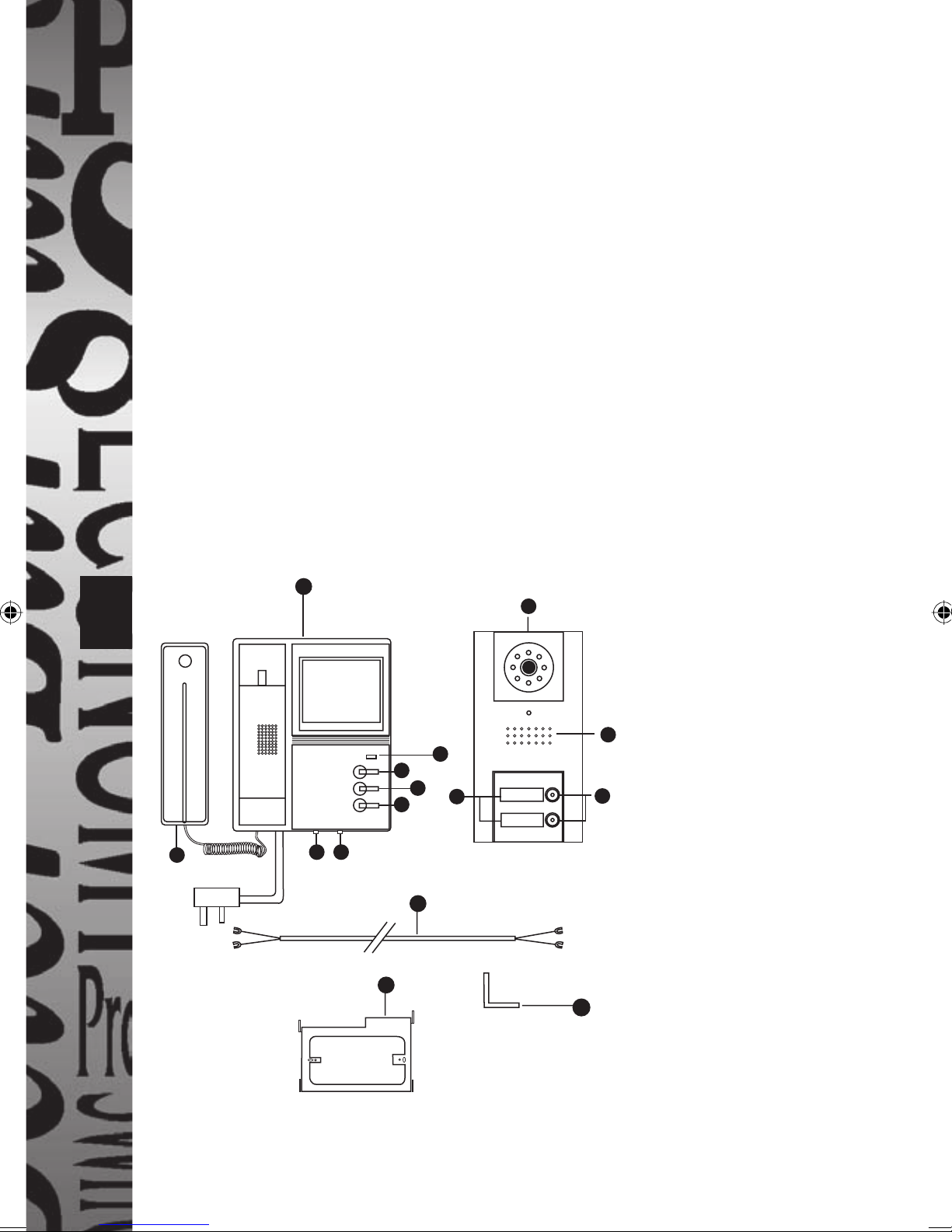
2. Product Overview
If operation with an electric door catch is required then part DCLR is a fail
(power off) secure catch available from Timeguard. An additional two core
cable run (using 13/0.2 bell fl ex) will be required between internal intercom and
1
door catch.
18
2
1
Fig 1 - Component Parts
1. External intercom.
2. Internal intercom.
3. Name plate.
4
5
11
12
13
3
NAME PLATE
NAME PLATE
4. Loudspeaker.
5. Mains on indicator.
6
6. Call button.
7. Keyhole fi xing.
16
14
8. Screw terminals.
9. Slot for angle bracket (15).
17
10. Wall mounting plate.
11. Monitor on button.
12. Monitor off button.
10
15
13. Door open button.
14. Brightness - three position
switch.
15. Angle bracket.
16. Volume adjust - three
position switch.
17. Connecting cable.
18. Internal intercom handset
Page 3

Fig 2 - Wiring diagram (DCC4 shown)
External intercom
Door catch
BROWN
RED BROWN
RED
BROWN
RED
RED
2
BROWN
6767
Internal intercom 2
(not for DCC3)
Internal intercom 1
Page 4

3. Selecting intercom sites and cabling
3.1 Intercom sites
The internal intercom should be located at a convenient position for all potential users
at the height indicated in fi g 3a and at a maximum distance of 70m from the external
intercom. If all the users are signifi cantly above or below average height then a different
mounting height may be considered appropriate.
The external intercom should be sited in an area away from driving rain
and surface water, out of direct sunlight as far as possible and protected by the
minimum of an open porch in a position readily accessible to potential entrants. It
should be mounted at the height indicated in fi g 3b.
3
50cm
135º
165
cm
Fig 3a
Internal intercom
mounting height
80cm
70º
165
cm
Fig 3b
External intercom mounting
height and coverage
3.2 Cabling
Connection between the internal and external intercoms is by 2 core cable.
A 15m length is supplied (2 for DCC4). A separation of intercoms up to 70m is possible.
Two core 13/0.2 bell fl ex is suitable. The cable run should be kept at least 100mm away
from any mains cable to avoid interference.
A second relatively short 2 core cable (13/0.2 bell fl ex) will be required between the
external intercom and the door catch (if needed).
A further 2 core cable (13/0.2 bell fl ex) will be required to extend (if necessary) the
cable between the external intercom and the second internal intercom for the DCC4.
Existing bell runs can be made use of.
Page 5

4. Fixing Intercoms
4.1 External intercom
Important: To give the best possible waterproofi ng and appearance we
recommend taking the wiring through the exterior wall directly over the wiring
terminals of the If the surface to be fi xed to is not even (e.g. pebbledash or
brickwork with raised pointing) we recommend the use of at least 10mm (3/8")
thick marine ply as a mounting plate between the wall and the intercom to
give a fl at surface for its 3 point fi xing.
Use the template provided to mark the positions of the three fi xing holes. Drill and, if
necessary, plug these holes for No. 8 roundhead screws.
Drive the top two No. 8 roundhead screws in leaving 3mm of the shank exposed (see fi g 4).
7
Fig 4
3mm
Wall surface
Fig 5
External
intercom
15
9
The third screw is used to secure the angle bracket (15) to the wall (see fi g 5).
Pass the cable(s) through the wall hole and terminate the cable from the internal intercom
ensuring that the brown and red wires are connected to the terminals of the same colour
on the external intercom (particularly important if an extension cable is used).
If a DCC4 is being installed then a second cable will be required to connect to the
additional internal intercom maintaining polarity as before.
If a door catch is to be used connect an additional two core cable to the terminals on the
external intercom marked door opener (not polarity conscious).
Offer up the external intercom to the fi xing points feeding the cable(s) back through the
wall as necessary. Locate the larger part of the keyhole fi xings on the heads of the two
fi xing screws (see fi g 5) and, keeping the rear of the case clear of the angle bracket (15),
push the external intercom downwards to locate the screws on the narrower part of the
keyhole fi xing.
4
Push the lower part of the external intercom towards the wall taking care
to locate the angle bracket (15) in the slot (9). Insert the screw supplied
through the countersunk hole in the lower edge of the external intercom and screw home.
If the fi xing surface is uneven it may be necessary to increase the exposed shank of one or
both of the top fi xing screws to get a satisfactory fi t.
Page 6

5
4.2 Internal intercom
Choose a position which can be reached easily by all potential users. If one person
usually in one location will be the main user it may be considered appropriate to locate
the internal intercom within reach of that person.
Mark out two holes suitable for No. 8 roundhead screws using the wall mounting plate
as a template (ensure this is the correct way up by referring to fi g 6).
Drill and plug the holes if necessary. Offer the wall fi xing
plate up to the wall and drive the fi xing screws home,
ensuring the plate is not distorted by mounting
on an uneven surface.
Connect the two core
lead from the external
intercom according
to fi g 2. Arrange this
cable and the mains
lead in the cable
Mounting slots
channel at the back
of the internal
intercom. Finally
locate the internal
intercom mounting
slots on the wall
fi xing plate
mounting hooks,
and slide intercom
downwards into
position.
Mounting hooks
Mounting
holes
Fig 6 - mounting
internal intercom
Cable
channel
Rear of internal
intercom
Mains lead
in cable
channel
Rear of wall
mounting plate
(this surface
facing wall)
4.3 Name Plates
Remove the transparent cover(s) using a small fl at bladed screwdriver as shown in fi g 7.
Lever out the plastic name plate(s) and mark as appropriate with a fi bre tipped pen
marked permanent.
Fig 7
1. Engage the screwdriver (fl at) blade in cover recess.
2. Push blade fi rmly into recess wall.
3. Maintaining pressure on recess lever cover
outwards against case.
Protect case under blade with card or
folded paper.
Page 7

5. Commissioning/Use
Press the call button (6) at the external intercom – a buzz will be heard locally and the
camera will activate for 1 minute. A ring tone will be heard at the internal intercom
for two to three rings and the display will show the visitor. Once the handset is lifted
two way communication is possible via the microphone and speaker at the external
intercom. To end the conversation and turn off the camera and display replace the
handset on hook. Finally, if a door catch is fi tted, the door open button (13) should be
pressed and, the door can be opened. It is not necessary for the handset to be lifted to
use the door open faciliity. The monitor on button (11) when pressed will give a minute
of camera and display active at any time. This can be brought to an end earlier by
pressing the video off button. If necessary the audio volume and video brightness can
be adjusted using the controls 16 and 14 respectively (fi g 1).
6. Do’s and Dont’s
1. Never use the product if it shows any signs of damage.
2. In case of damage to the product unplug the mains plug from the 13A socket
to avoid any possibility of electric shock and have the damage examined by a
competent person.
3. When laying cabling ensure that no cables (particularly mains cables) are damaged.
4. The mains supply to the internal intercom should be within the range 90 – 235V AC
50/60Hz.
5. The installation should only be carried out by a competent person.
6. The internal intercom should be kept out of reach of children and unauthorised
persons.
7. Keep low voltage cabling at least 100mm away from any mains cabling.
8. Ensure that all electrical connections are made and wires are arranged according to
the instructions.
9. Do not cover the louvres on the internal intercom.
7. Troubleshooting
No Audio or Video Check cable between internal and external
intercoms is connected correctly.
Check that there are no breaks or damage to the
interconnecting two core cable.
Check that the mains supply is plugged in and
switched on.
6
Door catch not working Check cable between external intercom and door catch
(if fi tted)
Check that terminations are correctly made at each
Check that the mains supply is plugged in and
for breaks or damage.
end of the above cable.
switched on.
Page 8

8. Cleaning
Unplug mains supply before cleaning product.
Clean internal and external intercoms with a damp cloth only – no cleaning agents.
Remove dust deposits from the louvres on the internal intercom with a soft brush or
vacuum cleaner.
9. Specifi cations
Mains supply: 90 – 235V AC 50/60Hz
Power consumption: Operating 4.5W
Standby 1W
Operating ambient temp range: -10°C to +50°C (external intercom)
+35°C max (internal intercom)
Ringtone volume: 80dBA at 0.3m maximum
(adjustable by 3 position switch)
Door catch: Max 12V DC 1A
3 Year Guarantee
7
In the unlikely event of this product becoming faulty due to defective material or
manufacture within 3 years of the date of purchase, please return it to your supplier in
the fi rst year with proof of purchase and it will be replaced free of charge. For years 2
and 3 or any diffi culty in the fi rst year telephone the helpline on 020 8450 0515.
Recycling
When service life is over please consult your local
authority regarding method of disposal.
HELPLINE
020-8450-0515
For a product brochure please contact:
Victory Park, 400 Edgware Road,
Timeguard Ltd.
London NW2 6ND
020-8452-1112
or email csc@timeguard.com
67-058-236
 Loading...