

Page 1
VIDEO DOOR ENTRY SYSTEM
Model: DCC1 Black and White
DCC2 Colour
DCC1/2
INSTALLATION & OPERATING INSTRUCTIONS
DCC1/2
Page 2
1
7
1. Introduction
The DCC1/DCC2 Door Entry System enhances entry security by enabling the user
to recognise the visitor by audible and viisual means before openiing the door.
The external intercom incorporates LED lighting to illuminate the visitor for the
camera. This type of lighting has an indefi nte life.
An electric door catch (not supplied) is available as an optional extra for the
DCC1/DCC2 to make the door opening automatic.
The external and internal intercoms are connected by a four core cable. With
the cable supplied the distance between these units is limited to 15m. By using
a larger core diameter cable this distance can be increased to a maximum of
100m, see section 9 (specifi cations) for further details.
2. Product Overview
If operation with an electric door catch is required then part DCLR is a fail
(power off) secure catch available from Timeguard. It requires an additional
mains adaptor part DCADAP to enable operation. See fi g 2 for wiring of these
parts. An additional two core cable run (using 13/0.2 bell fl ex) will be required
between internal intercom and door catch via the additional mains adaptor.
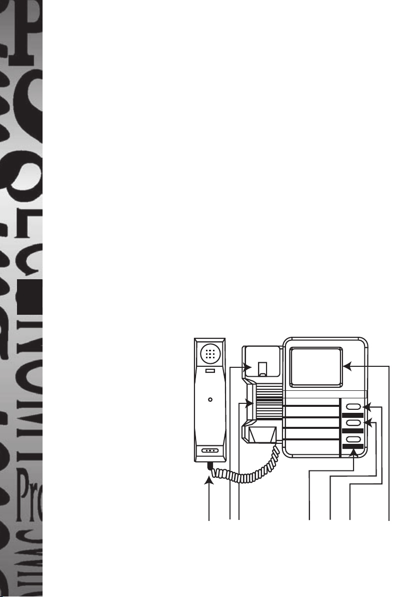
Fig 1a - Internal intercom
(Front view - mains
adaptor not shown)
1. Handset
2. Handset on-hook switch
3. Integral speaker
4. “Door Open” button
5. “Video Off” button
6. “Video On” button
7. Monitor screen
123 456
Page 3
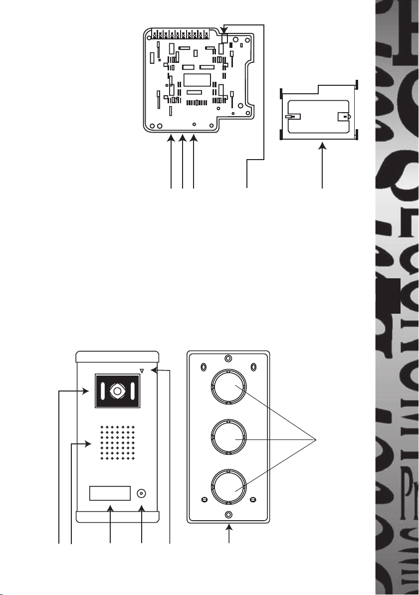
Fig 1b - Internal
intercom
(Rear view and wall
mounting plate)
8. Volume control
9. Brightness control
10. Contrast control
(colour control DCC2)
11. Mains adaptor low
voltage socket
12. Wall mounting plate
Fig 1c - External Intercom and Wall Box
a. Camera and LED lighting assembly
b. Integral speaker
c. Name plate
d. Call button
e. Integral microphone
f. Wall box
10 9 8 11 12
2
ab c d e f
Knock-outs for
cable entry
Page 4

Fig 2 - Wiring diagram
3
External intercom (rear
1R (red)
2W (white)
3B (brown)
4Y (yellow)
view)
Mains adaptor for door
catch (not supplied)
Part DCADAP
5K1
6K2
Electric door catch
(not supplied)
Part DCLR
Internal intercom
(rear view)
Mains adaptor
Page 5

3. Selecting intercom sites and cabling
3.1 Intercom sites
The internal intercom should be located at a convenient position for all potential
users at the height indicated in fi g 3a and at a maximum distance of 70m from
the external intercom. If all the users are signifi cantly above or below average
height then a different mounting height may be considered appropriate.
The external intercom should be sited in an area away from driving rain
and surface water, out of direct sunlight as far as possible and protected by the
minimum of an open porch in a position readily accessible to potential entrants.
It should be mounted at the height indicated in fi g 3b.
50cm
135º
165
cm *
Fig 3a
Internal intercom
mounting height
External intercom mounting
height and coverage
50cm
70º
165
cm *
Fig 3b
3.2 Cabling
Connection between the internal and external intercoms is by 4 core cable. A
15m length is supplied.
A separation of intercoms up to 100m is possible, refer to section 9
(specifi cations) to see how cable core diameter needs to be increased with
increasing separation.
The cable run should be kept at least 100mm away from any mains cable.
4
Page 6

5
4. Fixing Intercoms
4.1 External intercom
Important: To give the best possible waterproofi ng and appearance we
recommend taking the wiring through the exterior wall directly behind
the external intercom so that the cabling will feed directly through
a back box cable knock out. If the surface to be fi xed to is not even
(e.g. pebbledash or brickwork with raised pointing) we recommend
the use of at least 10mm (3/8") thick marine ply as a mounting plate
between the wall and the back box to prevent its distortion and loss of
waterproofi ng.
i Remove the back box from the external intercom in the following way. Insert
a small screwdriver blade in the end cap screwdriver notch (fi g 4, i) and lever
end cap so that it slides outwards from the main case (in opposite directions
to those shown in fi g 4, iv). Remove the two fi xing screws (as shown in fi g 4,
iii) and remove the back box from the rear of the external intercom.
ii This is a convenient time to mark the nameplate.
Referring to fi g 5, remove screw holding the PCB assembly to the transparent
housing. Lever one of the catches on the transparent housing clear of the
PCB assembly and lift the PCB assembly clear of the transparent housing.
Lever out the diffuser and nameplate from the transparent housing.
Mark the nameplate as required with a permanent fi bre-tipped pen. When
dry insert the nameplate into its recess in the housing ensuring it is the right
way up. Replace the diffuser on top of the nameplate and push the PCB
housing to engage with the catches of the transparent housing. Replace the
screw holding the transparent and PCB housings together.
iii Offer the back box up to the required position on the wall (refer to section
3.1). Decide which of the cable knock outs is to be used. Score around the
groove with a sharp knife and push the centre out. Feed the 4 core cable
through this knock out in the back box (see fi g 4, ii). Mark the positions of
the four fi xing screws (no 8 roundhead) using the back box as a template
(see fi g 4, ii). Remove the back box, drill and, if necessary plug holes.
Feed the cables through the wiring slot. Fix the back box to the wall with
No. 8 roundhead screws.
Page 7

Fig 4i
Fig 4ii
End plate
Screwdriver
notch
Fixing holes
Cable knock
outs
Fixing holes
Fig 4iii Fig 4iv
End cover
End cover
iv Make the necessary wire terminations (see
fi g 2) and offer the external intercom up to
the back box. Tighten the fi xing screws as
indicated (fi g 4, iii).
v Slide the two end covers inwards as shown
until fully home (see fi g 4, iv).
Fig 5 – Rear access to nameplate
PCB
assembly
Screw holding PCB to
transparent housing
6
Transparent
housing
Catches on
transparent
housing
Page 8

7
4.2 Internal intercom
Choose a position which can be reached easily by all potential users. If one
person usually in one location will be the main user it may be considered
appropriate to locate the internal intercom within reach of that person.
Mark out two holes suitable for No. 8 roundhead screws using the wall
mounting plate as a template (ensure this is the correct way up by referring
to fi g 6).
Drill and plug the holes if necessary. Offer the wall fi xing plate up to the
wall and drive the fi xing screws home, ensuring the plate is not distorted by
mounting on an uneven surface.
Connect the four core lead from the external intercom according to fi g 2. Plug
the mains adaptor low voltage plug into the mains adaptor socket (see fi g 1).
Arrange the two cables at the back of the internal intercom. Finally locate the
internal intercom mounting slots on the wall fi xing plate mounting hooks, and
slide intercom downwards into position.
Fig 6
Mounting slots
Mounting hooks
Rear of internal
intercom
Rear of wall
mounting plate
(this surface
facing wall)
Mounting holes
Page 9

5. Commissioning/Use
Press the call button (fi g 1c, d) at the external intercom – a buzz will be
heard locally and the camera will activate for 1 minute. A ring tone will be
heard at the internal intercom for two to 3 rings and the display will show
the visitor.
Once the handset is lifted two way communication is possible via the
microphone and speaker at the external intercom.
The video on button (fi g 1a, 6) when pressed will give a minute of camera
and display active at any time. This can be brought to an end earlier by
pressing the video off button.
To end the conversation and turn off the camera and display replace the
handset on hook.
Finally, if a door catch is fi tted, the door open button (fi g 1a, 4) should be
pressed and, the door can be opened.
It is not necessary for the handset to be lifted to use the door open faciliity.
If necessary the audio volume, video brightness and video contrast can be
adjusted using the controls 8, 9 and 10 respectively (fi g 1b).
8
Page 10

9
6. Do’s and Dont’s
1. Never use the product if it shows any signs of damage.
2. In case of damage to the product unplug the mains adaptor from the mains
supply to avoid any possibility of electric shock and have the damage
examined by a competent person.
3. When laying cabling ensure that no cables (particularly mains cables) are
damaged.
4. Never try to operate the mains adaptor at a voltage other than 230V 50Hz.
5. The installation should only be carried out by a competent person.
6. The internal intercom should be kept out of reach of children and
unauthorised persons.
7. Keep low voltage cabling at least 100mm away from any mains cabling.
8. Ensure that all electrical connections are made and wires are arranged
according to the instructions.
9. Do not cover the louvres on the internal intercom.
7. Troubleshooting
No Audio or video Check cable between internal and external intercoms
is connected correctly.
Check that there are no breaks or damage to the
interconnecting four core cable.
Check that the mains adaptor is plugged in and
switched on.
Door catch not working Check cable between external intercom and door
(if fi tted)
Check that terminations are correctly made at each
Check that both the mains adaptors are plugged in
catch for breaks or damage.
end of the above cable.
and switched on.
Page 11

8. Cleaning
Unplug mains adaptor before cleaning product.
Clean internal and external intercoms with a damp cloth only – no cleaning
agents.
Remove dust deposits from the louvres on the internal intercom with a soft
brush or vacuum cleaner.
9. Specifi cations
Mains adaptor: 230V 50Hz/15V, 1A
Secondary current: Operating 710mA DCC1,
100mA DCC2
Standby 160mA DCC1,
44mA DCC2
Max ambient temp: 35°C
DCC1 – Black & White
Monitor: 4" fl at black & white CRT, resolution 320 lines
Camera: F=2.0 lens, 1/4 CMOS image
DCC2 – Colour
Monitor: 3.5" fl at colour LCD, resolution 480 x 234 dots
Camera: F=2.0 lens, 1/3 CMOS image
Operating ambient temp: -10°C to +55°C DCC1, -10°C to +45°C DCC2
Door Catch: Max 12V DC 1A
10
The table below gives the minimum diameter for each core in the four core
cable for various distances between the indoor and outdoor intercoms
(monitor and camera).
Distance between the camera
and the monitor
From 1m to 20m 0.45mm
From 20m to 50m 0.50mm
From 50m to 100m 0.75mm – 1mm
Diameter for each wire
inside the cable
Page 12

11
3 Year Guarantee
In the unlikely event of this product becoming faulty due to defective material
or manufacture within 3 years of the date of purchase, please return it to your
supplier in the fi rst year with proof of purchase and it will be replaced free of
charge. For years 2 and 3 or any diffi culty in the fi rst year telephone the helpline
on 020 8450 0515.
Recycling
When service life is over please consult your local
authority regarding method of disposal.
HELPLINE
020-8450-0515
For a product brochure please contact:
Timeguard Ltd.
Victory Park, 400 Edgware Road,
London NW2 6ND
020-8452-1112
or email csc@timeguard.com
67-058-233
 Loading...