

Page 1
Presence detector
ECO-IR 180A
ECO-IR 360A
Art. Nr. 202 0 050
Art. Nr. 202 0 000
Bedienungsanleitung 2
D
F
Notice d
GB
Installation manual 4
E
Manual de instrucciones 6
I
Istruzioni per l'uso 8
NL
Gebruikershandleiding 102
´utilisation 22
2
2
2
1103000311 © 11.08 Theben HTS
Page 2

English
Installation manual
Presence detector
ECO-IR 180A
ECO-IR 360A
Table of contents
1. Safety . . . . . . . . . . . . . . . . . . . . . . . . . . . . . . . . . . . . . . . . . . . . . . . . . . 43
2. Function and performance characteristics. . . . . . . . . . . . . . . . . . . . . . . 44
3. Detection Range . . . . . . . . . . . . . . . . . . . . . . . . . . . . . . . . . . . . . . . . . . 46
4. Mounting and connecting the device . . . . . . . . . . . . . . . . . . . . . . . . . . . 48
5. Start-up . . . . . . . . . . . . . . . . . . . . . . . . . . . . . . . . . . . . . . . . . . . . . . . . . 50
6. Technical specications . . . . . . . . . . . . . . . . . . . . . . . . . . . . . . . . . . . . . 54
7. Warranty declaration . . . . . . . . . . . . . . . . . . . . . . . . . . . . . . . . . . . . . . . 56
8. Troubleshooting . . . . . . . . . . . . . . . . . . . . . . . . . . . . . . . . . . . . . . . . . . . 57
42
Page 3

Thank you for choosing a Theben HTS presence detector and putting
your trust in us.
1. Safety
DANGER !
Any work on electrical systems must exclusively be carried out by qualied
electricians or instructed persons under the direction and supervision of a
qualied electrician in accordance with the relevant electrotechnical rules!
Any national safety regulations regarding the manipulation of electrical
systems must be observed! The voltage supply must be disconnected
prior to installation!
CAUTION !
The device is maintenance-free. The warranty terminates if the device is
opened or entered with any kind of object.
Designated use
The presence detector is solely intended for the purpose contractually specied between the manufacturer and the user. Any other or extended use
has to be regarded as not complying with the designated use. The manufacturer is not liable for any resulting damage.
GB
43
Page 4

2. Function and performance characteristics
2.1 Presence detection
High-sensitivity PIR sensors and an intelligent lens system provide complete
coverage.
2.2 Integrated daylight measurement
Measures the exact amount of daylight independently of the articial lighting
conditions. The measurement is performed in the viewing direction of the
device. Delayed response to brightness changes to prevent unnecessary activation/deactivation.
2.3 Switching contact «Light»
The switching contact closes if the brightness level is too low and if the presence of a person is detected. It opens if the brightness level is adequate or
if no presence is detected. The switch-off delay time and desired switching
value can be dened as required.
The ECO-IR is designed for use in combination with uorescent
lamps (FL operates with standard ballasts) and energy saving
lamps (PL). Incandescent or halogen lamps may interfere with the
operation of the detector.
With indirect lighting, ensure that the main part of the light from these lamps
is not directed at the detector as this affects the daylight measurement.
44
Page 5

When using suspended lighting, we recommend that you integrate the detector directly in the lamps or provide a sufcient lateral clearance. When
using suspended lighting, note that the detection range may be shaded.
2.4 Switching contact «HVAC»
A potential free relay connects loads up to max. 100 W. The loads are only
connected if a person is detected, independent of the incident daylight. The
contact is closed if persons are detected.
2.5 Switch-off delay time «Light»
You can set the minimum duration to between 2 and 15 minutes. The ECO-
IR can extend this time setting (by max. 15 minutes) or reduce it to the
minimum value, depending on the frequency of movement (self-learning
effect). When set to 2 minutes, the switch-off delay is xed.
2.6 Switch-off delay time «HVAC»
You can set the duration steplessly to between 10 and 60 minutes. Unlike the
«Light» switch-off delay time, the «HVAC» switch-off delay time is not adjusted
by the ECO-IR.
The switch-off delay times are restarted each time a movement is detected.
GB
45
Page 6

3. Detection Range
3.1 Detection Range ECO-IR 180A for wall mounting
The recommended mounting height is 2,2m. Mounting the device in the
height of the switches is not recommended (possible obstacles, vandalism).
M’height Seated persons Walking persons
2,2m 8,0m x 4,0m approx. 8m radial distance
Due to the horizontal orientation of the ECO-IR 180A, the detection
range is very large. The sensitivity decreases by increasing distance.
3.2 Detection Range ECO-IR 360A for ceiling mounting
The ideal mounting height is 2,0 - 3,5m.
The sensitivity of the detector decreases with increasing mounting height.
In order to ensure proper detection of persons, the ECO-IR 360A requires
an unobstructed “view” of the persons. Ofce equipment, plants, suspended
lamps etc. may affect the presence detection (shading).
M’height Seated persons Walking persons
2,0m 4,5m x 4,5m 6,0m x 6,0m ± 0,5m
2,5m 6,0m x 6,0m 8,0m x 8,0m ± 0,5m
3,0m 7,0m x 7,0m 9,0m x 9,0m ± 0,5m
3,5m 8,0m x 8,0m 10m x 10m ± 1,0m
4,0m --- 11m x 11m ± 1,0m
46
Page 7

ECO-IR 180A: ECO-IR 360A:
o
2,2 m
1 2 3
5
6 7 80
4
0
2
1
3
o
GB
47
Page 8

4. Mounting and connecting the device
3
4.1 Type of mounting
Both ECO-IR models must be mounted in housings (surface-mounted or concealed installation, single housing). Suitable hollow-wall housings must be
provided for mounting the devices in suspended ceilings.
4.2 Preparations
First pull out the left and right-hand safety locks up to the limit stop using a
screwdriver to separate the sensor head from the power section.
Remove the sensor head from the power section.
48
Page 9
L N
B1 B2
L
N
ECO-IR 540B2
A
ECO-IR 540B2
L N
A
L
N
ECO-IR 540B2
L N
A
B1 B2 B1 B2
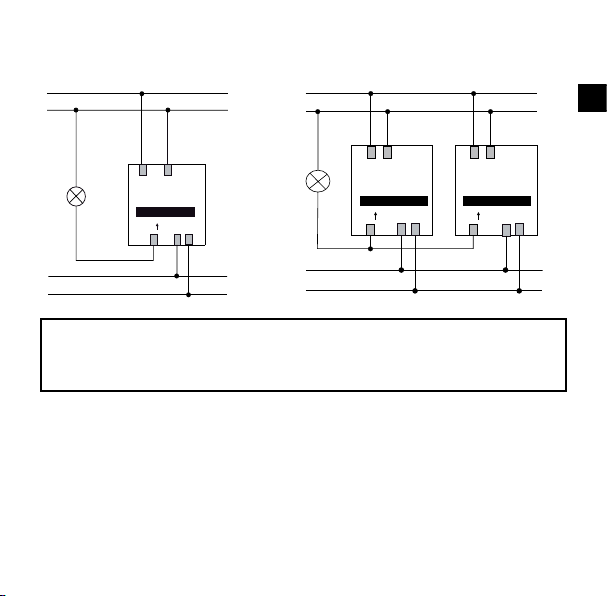
4.3 Connecting the ECO-IR
Connect the power section of the ECO-IR 540B2 as shown in the diagram:
GB
HVAC
HVAC
All of the ECO-IR units connected in parallel must be con-
4.4 Stepping switch/time switches
The ECO-IR must not be used to trigger stepping switches. The unit may
only be connected in parallel to time switches.
4.5 Inductive loads
Inductive loads must be interference-suppressed with suitable spark extin-
nected to the same mains phase. The overall permissible
load as a result of the parallel connection is not higher.
guishers (e.g. RC combination)
49
Page 10

5. Start-up
30
10
5.1 Settings
Set the unit as shown on the rear of the disassembled sensor head. Note the
setting guidelines in the following tables for dening the default settings.
Switch-off delay time «HVAC»
Set the desired switch-off delay time for the „HVAC“ switching contact on the
potentiometer. The preset values remain unchanged (no self-learning effect)
●
Switch-off delay time depending on application and load 10 - 60 min.
50
Page 11

Switch-off time delay «Light»
Set the desired minimum switch-off delay time for the «Light» switching
contact on the potentiometer.
●
Transfer zones approx. 5min.
●
Working areas approx. 10min.
The setting corresponds to the minimum value. The effective switch-off de-
lay time varies between the set value and the maximum value of 15 min.
(self-learning effect). When set to 2 min., the switch-off delay is xed.
Brightness threshold «LUX» Scale
Transfer zones (no working area) approx. 2
●
Working areas (ofces, conference rooms) approx. 4
●
Activities requiring good visibility (laboratory, drawing) > 5
●
Deactivation of brightness measurement «on»
●
Depending on the installation location, natural light intensity, furniture, reection characteristics of the room and the furniture it may be necessary to
correct the settings by 1-2 steps on the scale.
GB
51
Page 12

5.3 Behaviour on switching on
After you have dened the settings, connect the upper part to the power
●
section. Ensure that the labelling is aligned on both parts.
Each time the sensor head is attached to the power section or after the
●
power supply is connected, a startup phase (90 sec.) followed by a ser-
vice phase (10 min.) is initiated on the sensor. The sensor then switches
to normal operation automatically.
Avoid using force when assembling the unit. Ensure that the two
parts are aligned correctly.
Do not press on the lens. Hold the upper part at the white edge only.
●
The two switching contacts are closed for approx. 90 sec. after the unit
●
has been assembled (startup phase).
The lighting system lights up continuously and the ventilation system is
●
in operation.
In the subsequent service phase, the ECO-IR responds immediately to
●
changes in brightness in order to test the set brightness switching value
(Lux) quickly.
If the room is darkened (e.g. by closing the blinds), the lighting system
●
is switched on when the switching value is reached. The lights can be
switched off by „blinding“ the sensor with a torch.
52
Page 13

The service phase is completed automatically after 10 minutes.
●
Repeat the setting procedure if it is necessary to modify one of the three
●
variables.
Push the safety lock inwards as far as possible after the test (between
●
the sensor head and the power section). The detector is then ready for
operation.
5.4 Disassembling/readjusting the unit
If you want to disassemble the head section or change the settings, rst
●
open the safety locks by pulling out the two locks with a screwdriver.
GB
53
Page 14

6.Technicalspecications
Sensor module ECO-IR 180A
Detection range horizontal
Recommended mounting height ca. 1,6m - 2,2m
Maximum range < 10m
Daylight measurement
Light measurement deactivated
Switch-off delay time for light 2min. - 15min.
Switch-off delay time for presence / HVAC 10min. - 60min.
Sensor module ECO-IR 360A
Detection range horizontal
vertical
Recommended mounting height 2,0m - 3,5m
Maximum range 8 x 8m (Mh. 2,5m)
Daylight measurement
Light measurement deactivated
Switch-off delay time for light 2min. - 15min.
Switch-off delay time for presence / HVAC 10min. - 60min.
*) Use of T5-FL: When using T5-FL lamps with a comparable wattage, the same number
of electronic ballasts may be connected to the detector’s switching contact as for the T8-
FL. When using the 80W-FL, the number should be halved in comparison to the 58W-FL.
54
180º
ca. 50 - 1600Lux
„on“
360º
120º
9 x 9m (Mh 3,0m)
ca. 50 - 1600Lux
„on“
Page 15

Common power module ECO-IR 540B2
Nominal voltage 230V± 10%, 50Hz
Switching contact A
Contact design 230V± 10%
Max switching capacity 1400VA
Max. nr. of electronic ballasts *)
(A relay or contactor must be connected in case of
more powerful devices)
Switching contact B
Contact design, potential free
Class of protection II
Recommended max. load 100W / 460VA
Mounting depth
Mounting diameter
Mounting plate (integrated)
Screwless terminals (rigid connectors) max. 1.5mm²
Size of concealed housing Size 1, (NIS, PMI)
Ambient temperature 0º to 50º C
Degree of protection IP 40
Article numbers
ECO-IR 180A 202 0 050
ECO-IR 360A 202 0 000
Surface frame ECO-IR 180 907 0 511
Surface frame ECO-IR 360 907 0 512
«Light»
12x (1x58W); 6x 2x58W)
18x (1x36W); 9x 2x36W)
18x (< 36W)
«HVAC»
24V @ 2A m, 230V~2A m
EN 60730-1
35mm
55mm
70x70mm
GB
55
Page 16

7. Warranty declaration
Theben HTS presence detectors are manufactured and quality-tested with the utmost
care using state-of-the-art technologies. Theben HTS therefore guarantees perfect
function, provided the detectors are used as intended. However, should a defect occur,
Theben HTS offers the following warranty within the scope of its General Terms and
Conditions of Business:
Please bear in mind the following points:
The warranty period is 24 months, commencing from the manufacturing date.
●
The warranty becomes null and void if you or third parties undertake alterations to
●
the units.
If the presence detector is connected to a software-controlled system, the warranty
●
for this connection is only valid provided the stated interface specication is
adhered to.
We undertake to repair or replace as quickly as possible all supplied components which
have become defective or unusable as a result of demonstrably bad material, faulty
design or defective workmanship up to the expiry of the warranty period.
Returns
In the event of a warranty claim please send the unit together with the delivery note and
a brief description of the fault to the dealer concerned.
Industrial property rights
The concept including hardware and software of these units is protected by copyright.
56
Page 17

8. Troubleshooting
Fault Cause Remedy
Lighting on after
the detector is
connected.
Immediate response to change
in brightness
Lights never
switched on,
despite presence
of persons and
little daylight
Lights ash
constantly
(«blinking»)
Lights on continuously / detector switches
without reason
Lights extinguish
despite presence
of persons
Detection zone
is smaller than
specied
Both outputs are closed for 90
s after the detector has been
connected (test phase)
The device is in service phase
(10 min.). This phase is used
to adjust the brightness setting
1. Lux value too low.
2. Detection zone does not
cover the entire room. Vision
may be impaired.
1. Halogen or incandescent
lamps triggered by ECO-IR.
2. Direct illumination from
uorescent lamps too high.
1. Lux value too high.
2. Other movements have
been registered.
3. External contactor or relay
triggered
4. Several detectors connected
in parallel
Minimum switch-off delay time
too low
1. Objects in visibility range
2. Detector positioned incor-
rectly
Wait for 90 s. The device then
responds immediately to changes in
brightness for 10 minutes.
After the service phase, the re-
sponse to a change in brightness is
delayed to prevent sudden switching.
1. Increase Lux value.
2. Change mounting location or
remove obstacles in detection range.
1. Set Lux value to „on“ or replace incandescent lamps with FL/PL lamps.
2. check arrangement of detector
with regard to lamps.
1. Decrease Lux value.
2. Devices with instant heat emission
(e.g. heater), moving objects (curtains, etc.) or domestic animals?
3. Fit inductive loads with spark
extinguishers (e.g. RC element).
4. Check Lux setting on detectors
Check recommended settings, incre-
ase switch-off delay time.
1. Remove obstacles, replace detector
2. Check detection range
GB
57
Page 18

Dimensions ECO-IR 180A
5
6
1
1
4
7
0
70
56
46,3
35
80
48
70
45
85
Subject to change without prior notice. Errors and omissions excepted.
58
Page 19
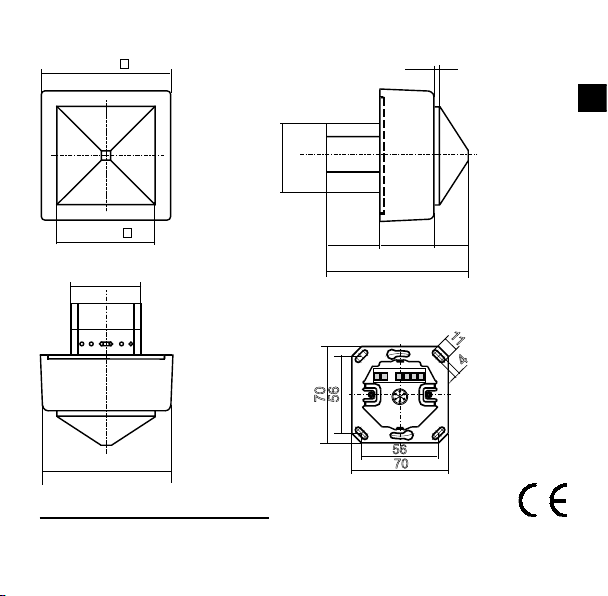
Dimensions ECO-IR 360A
87
35,5
95
46,3
48
84,5
66,5
37,5
22
4
5
6
1
1
4
7
0
70
56
GB
Declaration of CE conformity
This device complies with the protection regulations of the EMC directive 2004/108/EC
and of the Low Voltage directive 2006/95/EC.
59
Page 20

Theben AG
Hohenbergstrasse 32, DE-72401 Haigerloch
Tel. +49 (0) 74 74 692 - 0
Fax +49 (0) 74 74 692 - 150
Hotline
Tel. +49 (0) 74 74 692 - 369
Fax +49 (0) 74 74 692 - 207
hotline@theben.de
Switzerland
Theben HTS AG
Im Langhag 11, CH - 8307 Effretikon
Tel. +41 (0)52 355 17 00
Fax +41 (0)52 355 17 01
www.theben-hts.ch
Die Kontaktadressen für weitere Länder nden Sie auf www.theben.de
Veuillez compulser les adresses pour des pays supplémentaires sur www.theben.de
Please nd the contact addresses for additional countries on www.theben.de
Las direcciones de contacto de otros países las encontrará en www.theben.de
Gli indirizzi per ulteriori paesi sono disponibili su www.theben.de
De contactadressen voor andere landen vindt u op www.theben.de
60
 Loading...