

Page 1
Presence detector
compact passage
Art. Nr. 201 0 090
Bedienungsanleitung 2
D
Notice d´utilisation 22
F
Installation manual 42
GB
Manual de instrucciones 62
E
I
Istruzioni per l'uso 82
NL
Gebruikershandleiding 102
1103023503 / 09.08 © Theben HTS
Page 2

English
Installation manual
Presence detector
compact passage
Table of contents
1. Safety ..................................................39
2. Function and performance characteristics. . . . . . . . . . . . . . . . . . . . . . . 40
3. Fitting and connection ......................................41
4. Start-up .................................................43
5. Additional wiring examples ..................................47
6. Test mode ...............................................50
7. Technical specications .....................................51
8. Warranty declaration .......................................53
9. Troubleshooting ...........................................54
42
Page 3

Thank you for purchasing an Theben HTS presence detector and putting
your trust in us.
1. Safety
DANGER !
Any work on electrical systems must exclusively be carried out by qualied
electricians or instructed persons under the direction and supervision of a
qualied electrician in accordance with the relevant electrotechnical rules!
Any national safety regulations regarding the manipulation of electrical systems must be observed! The voltage supply must be disconnected pri-
or to installation!
CAUTION !
The device is maintenance-free. The warranty terminates if the device is
opened or entered with any kind of object.
Designated use
The presence detector is solely intended for the purpose contractually spe-
cied between the manufacturer and the user. Any other or extended use
has to be regarded as not complying with the designated use. The manufacturer is not liable for any resulting damage.
GB
43
Page 4

2. Function and performance characteristics
The presence detector compact passage is used for a comfortable and efcient light as well as HVAC control within a corridor.
The switching contact A «Light» switches on the lighting in case of presence and insufcient brightness, and off in case of absence or sufcient
brightness. In addition, the lighting can be switched manually by means of
push-buttons.
●
Switching contact «Light»: relays 230V
●
Manual control by push-button or switch
●
Semi or fully automatic operation
●
Push-button function: room / corridor
●
Suitable for uorescent lamps, compact energy saving lamps as wells as
for halogen and incandescent lamps
●
Pulse function for staircase lighting timer
The switching contact B «Presence» controls heating, ventilation and airconditioning systems. The contact closes in case of presence, a switch-on
delay allows a delayed switching on. The contact can also be used for room
surveillance purposes. Using reduced sensitivity, it only responds on very
distinct movements.
●
Switching contact «Presence», potential-free relay
●
Adjustable switch-on delay and switch-off delay
●
Surveillance function
44
Page 5
3. Fitting and connection
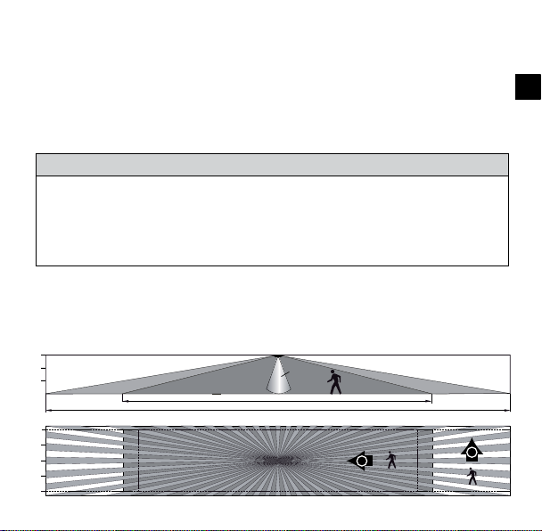
3.1 Presence detection
The ideal mounting height is 2,0 - 3,5m. The sensitivity of the detector decreases with increasing mounting height. The detection ranges of multiple
detectors should overlap in their fringe zone. Ensure the horizontal installation of the detector.
M'height radial (r) tangential (t)
2,0m 16,0m x 3,5m ± 1m 30,0m x 3,5m ± 1m
2,5m 18,0m x 4,0m ± 1m 30,0m x 4,0m ± 1m
3,0m 20,0m x 4,5m ± 1m 30,0m x 4,5m ± 1m
3,5m 20,0m x 5,0m ± 1m 30,0m x 5,0m ± 1m
Because of the virtually horizontal detection of compact passage to both
directions, the detection range of tangential (t) movements of persons is
different to the range of radial (r) movements towards the detector.
Detection range (mounting height 3,0m)
3
2
1
0
15m 12 10 8 6 4 2 0 2 4 6 8 10 12 15
2
1
0
1
2
15 14 13 12 11 10 9 8 7 6 5 4 3 2 1 0 1 2 3 4 5 6 7 8 9 10 11 12 13 14 15
Lux
r
t
GB
45
Page 6
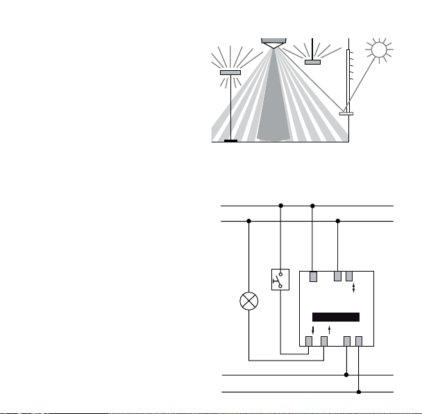
3.2 Light measurement
L
The detector measures articial light
and daylight reected directly bene-
ath the detector (beam width approx.
± 30°).
The mounting location is used as the
reference for the lighting levels.
With indirect lighting, the articial light at the detector’s mounting location
should not exceed 2000 Lux (Brightness value > 2000 Lux).
3.3 Connection
A concealed housing should be used
for ush-mounted tting of the presence detector compact passage.
A surface frame is available for surface mounting.
46
N
Presence (e.g. HVAC)
NL
compact
power
Master
SAPB2B1
Page 7

4. Start-up
The detectors are supplied ready for operation with a factory setting of recommended standard values.
The QuickSet plus service remote control for starting-up the system is optionally available. With the remote control all potentiometer values can be set
from a distance.
4.1 Settings for switching contact A «Light»
Potentiometer
Brightness threshold “LUX” Scale
Transfer zones (no working area) approx. 2
●
Bright transfer zones approx. 4
●
Deactivation of brightness measurement “on”
●
Depending on the installation location,
natural light intensity, furniture, reection characteristics of the room and the
furniture it may be necessary to correct
the settings by 1-2 steps on the scale.
For ease of setting up, we recommend
the service remote control QuickSet
plus.
GB
47
Page 8

Switch-off delay time
●
Transfer areas approx. 5min.
●
In the range between 2 - 15min the switch-off delay varies according to
its self-learning behavior. The set values <2min or >15min remain xed.
●
«Pulse»: staircase lighting timer control (0.5s “on” / 10s “off”)
DIP switch
Fully / Semi-automatic mode
●
«auto»: Fully automatic mode. The lighting is switched on automatically.
●
«man»: Semi-automatic mode. The lighting must be switched on manually .
Push-button function: room / corridor
●
«room»: Manual switching on/off possible.
●
«corridor»: Detector is used as staircase lighting timer.
No manual switching-off possible.
Push-button/Switch control
●
Optional push-button or switch operation.
●
Multiple push-buttons on one control input possible.
●
Use illuminated push-buttons with PEN conductor connection only.
48
Page 9

4.2 Settings for switching output B «Presence»
Switch-off delay time for presence
The pre-set values remain unchanged (no self-learning effect).
●
Switch-on delay time for presence
In case of presence, the contact does not close before the set switch-on
●
delay has elapsed.
0 = Contact closes immediately in case of presence.
●
Room surveillance function; the contact closes only in case of
●
distinct movements (effective protection against false alarms).
GB
49
Page 10

4.3 Behaviour on switching on
Whenever the sensor module is plugged onto the power module or the unit
is energised, the detector goes through tree phases which are indicated by
an LED.
1. Start-up phase (30sec)
LED ashes every second, both contacts are closed
●
(light and presence on)
In case of absence, both contacts open after 30sec.
●
2. Service phase (10min)
The «Light» contact reacts instantaneously on brightness in order to
●
check the brightness threshold.
If the brightness is insufcient the lighting is switched on (LED on),and if
●
the brightness is sufcient the lighting is switched off (LED off).
During the service phase, switching of the lighting occurs fully automati-
●
cally (no semi-automatic mode).
The service phase terminates earlier by actuating the push-button or the
●
remote control.
3. Operation
The detector is ready for operation (LED off).
●
50
Page 11

5. Additional wiring examples
L
5.1 Master-Slave parallel circuit operation
Multiple detectors control one lighting group
●
Only the master switches the lighting. All other detectors serve as
slaves.
●
Presence detection is done by all detectors together.
●
Light measurement occurs on the master only.
●
Only set the potentiometer and DIP switches on the master.
●
Max. 10 detectors can be connected in parallel.
●
Use the same phase for all detectors.
●
Mark the power modules as master or slave respectively.
N
Presence (e.g. HVAC)
NLSAP
compact
power
Master
B2B1
NLSAP
compact
power
Slave
B2B1
Master
Master
Slave
GB
Slave
Lux
DIP
Master
Slave
DIP
51
Page 12

5.2 Master-Master parallel circuit operation
Master
Multiple masters control multiple lighting groups
●
One master with individual brightness measurement per lighting group.
●
Presence detection is done by all detectors together.
●
Potentiometer and DIP switches are set on each master individually.
●
Max. 10 detectors can be connected in parallel.
●
Use the same phase for all detectors.
●
The switching contact «Presence» can be tapped on any master.
●
Mark the power modules as master or slave respectively.
L
N
Presence (e.g. HVAC)
52
NLSAP
compact
power
Master 1
NLSAP
compact
power
Master 2
B2B1
B2B1
Master
Master
Slave
Lux
DIP
Master
Slave
Lux
DIP
Page 13

5.3 Parallel circuit operation with external staircase lighting timer
●
Directly connect the switching
contacts of multiple detectors in
parallel.
●
Set the switch-off delay on all
detectors to “pulse”.
●
Mark all power modules as
master.
●
Staircase lighting timer e.g. Theben ELPA 1
L
N
ELPA 1
out in
NL
compact
power
Master
NLSAP
compact
power
Master
B2B1NLSAPB2B1
5.4 Detector as staircase lighting timer
●
The master directly controls
the lighting.
●
The push-button starts the
master’s switch-off delay.
●
Set DIP switch to “corridor”
to prevent switching off via
push-button.
●
Further slaves can be connected in parallel using the P-terminal if required
●
Only set the potentiometer and DIP switches on the master.
●
Mark the power modules as master or slave respectively.
L
N
NLSAP
compact
power
Slave
B2B1
compact
power
Slave
B2B1NLSAPB2B1
SA
compact
power
Master
P
NL
GB
53
Page 14

6. Test mode
The test mode serves to check the presence detection and the wiring
(Master-Slave parallel circuit operation).
6.1 Setting the test mode with DIP-Switch
●
Set DIP switch to «Test» (on all detectors in parallel circuit operation).
1. Start-up phase (30sec)
●
Both contacts are closed for 30sec. (LED 20s «on», 10s «off» )
2. Test mode
●
In case of movement (LED on), both contacts close.
●
In case of absence (LED off), both contacts open after 10sec.
●
NOTE: no brightness measurement, detector always in fully automatic mode.
●
The detector remains permanently in the test mode.
6.2 Setting the test mode with QuickSet plus
●
While setting the test mode with the service remote control QuickSet
plus, the detector jumps the start-up phase and changes directly into the
test mode.
●
Test mode ceases automatically after 10 minutes. The detector performs
a reset (see section 4.3).
54
Page 15

7. Technical specications
Sensor module compact passage
Detection range horizontal
vertical
Recommended mounting height 2,0 - 3,5m
Maximum range 30 x 4 m (Mh. 2,5m)
Mixed light measurement
Light measurement deactivated
Switch-off delay time for light
Short pulse
Switch-off delay for „Presence“ 10sec. - 120min.
Switch-on delay for „Presence“
Room surveillance
Power module compact power
Mains voltage 230V ± 10%, 50Hz
Relais output A for «Light» 230V ± 10%
In-line fuse max. 10A
Max. switching capacity
Incandescent lamps, halogen
Max. nr. of electronic ballasts *)
(A relay or contactor must be connected
in case of more powerful devices)
360°
160°
30 x 5 m (Mh. 3,5m)
ca. 10 - 1500Lux
„on“
10sec. - 20min.
0.5sec. „on“/ 10sec. „off“
0sec. - 10min.
1400VA
1200W
10x (1x58W); 5x (2x58W)
16x (1x36W); 8x (2x36W)
16x (< 36W)
GB
55
Page 16

Relais output B for «Presence» potential-free
Maximum voltage 220V DC / 250V AC
Maximale switching capacity 50W / 50VA
Recommended minimum load 0.5mV / 10mA
Depth
Diameter
Mounting place
Screw terminals max. 2x 2.5mm2
Size of concealed housing Size 1, (NIS,PMI)
Ambient temperature 0° - 50°C
Degree of protection IP 40
Article numbers
compact passage 201 0 090
Surface frame for compact 907 0 514
Service remote control QuickSet plus 907 0 532
User remote control clic 907 0 515
*) Use of T5-FL: When using T5-FL lamps with a comparable wattage, the same
number of electronic ballasts may be connected to the detector’s switching contact as
for the T8-FL. When using the 80W-FL, the number should be halved in comparison to
the 58W-FL.
40mm
48mm
70 x 70mm
CE Declaration of Conformity
This device complies with the protection regulations of the EMC directives
2004/108/EC and of the Low Voltage directive 2006/95/EC.
56
Page 17

8. Warranty declaration
Theben HTS presence detectors are manufactured and quality-tested with the utmost care using state-of-the-art technologies. Theben HTS therefore guarantees
perfect function, provided the detectors are used as intended. However, should a defect occur, Theben HTS offers the following warranty within the scope of its General
Terms and Conditions of Business:
Please bear in mind the following points:
The warranty period is 24 months, commencing from the manufacturing date.
●
The warranty becomes null and void if you or third parties undertake alterations to
●
the units.
If the presence detector is connected to a software-controlled system, the war-
●
ranty for this connection is only valid provided the stated interface specication is
adhered to.
We undertake to repair or replace as quickly as possible all supplied components which
have become defective or unusable as a result of demonstrably bad material, faulty
design or defective workmanship up to the expiry of the warranty period.
Returns
In the event of a warranty claim please send the unit together with the delivery note and
a brief description of the fault to the dealer concerned.
Industrial property rights
The concept including hardware and software of these units is protected by copyright.
GB
57
Page 18

9. Troubleshooting
Fault Cause
Lighting does not switch on
or switches off in case of
presence and darkness
With persons present, the
lighting is on although the
brightness is sufcient
Lighting does not switch off
or switches on spontaneously in case of absence
Lighting keeps switching
on and off during the
service phase
Push-button does not work Device is still in start-up phase or an illuminated push-
Lighting cannot be switched
off with the push-button
Device does not respond Short circuit/ multiple phases connected in parallel!
Error blinking (4x per sec.) Failure during self test. Device not working!
58
Lux value setting is too low; Detector is in semi-automatic mode; Lighting was switched off manually; Person is
outside the detection range; Detection is disturbed by
obstacle(s); Set switch-off delay setting is too short
Lux value setting is too high; The lighting has been
switched on manually with clic recently (wait for 30
min); Detector is in test mode
Wait until the switch-off delay time has elapsed (selflearning effect); Disturbing heat sources within the
detection range (heaters, incandescent lamp/halogen
lamp, moving objects (e.g. curtains due to open
windows); Load (el. starter devices, relay) has no
interference suppression
Too much articial light is falling on the detector. Increase lux value or reposition the detector.
button without PEN conductor connection is used;
Push-button is not connected to the master
DIP-switch in „corridor“ position
Disconnect detector from mains for 5 min. (thermal
protection switch).
Page 19

Dimensions compact passage
26,5
44
40,5
102,5
76
∅
66
40
48
46
90
63
Subject to change without prior notice. Errors and omissions excepted.
GB
75
59
Page 20

Theben AG
Hohenbergstrasse 32, DE-72401 Haigerloch
Tel. +49 (0) 74 74 692 - 0
Fax +49 (0) 74 74 692 - 150
Hotline
Tel. +49 (0) 74 74 692 - 369
Fax +49 (0) 74 74 692 - 207
hotline@theben.de
Switzerland
Theben HTS AG
Im Langhag 11, CH - 8307 Effretikon
Tel. +41 (0)52 355 17 00
Fax +41 (0)52 355 17 01
www.theben-hts.ch
Die Kontaktadressen für weitere Länder nden Sie auf www.theben.de
Veuillez compulser les adresses pour des pays supplémentaires sur www.theben.de
Please nd the contact addresses for additional countries on www.theben.de
Las direcciones de contacto de otros países las encontrará en www.theben.de
Gli indirizzi per ulteriori paesi sono disponibili su www.theben.de
De contactadressen voor andere landen vindt u op www.theben.de
60
 Loading...